20
Calibration and Operation
US
SM5000 Sampling Module - DC Pump Model
3 Calibration and Operation
3.1 Introduction
Calibration of the sensor when used with the Pump Sampling Module should follow the operating instruc-
tions for the gas monitor used.
If this calibration procedure cannot be performed at any step, consult chapter 4.3 "Troubleshooting Guide-
lines", localize the problem and replace the inoperative component.
MSA offers periodic service that is available on a contract basis; for more information, please call MSA at
1-800-MSA-INST.
3.2 Calibration Procedures
Place the instrument receiving the signal from the gas monitor into calibration mode, if applicable.
WARNING!
It is necessary to put the receiving instrument in calibration mode. If the instrument is not in calibration
mode, any alarm relays may energize and activate any safety devices which are connected to the alarm
relays of the instrument.
Equipment needed:
• Ultima X (calibration kit #42)
X5000/S5000 (CALKIT2)
• Appropriate zero and span gas cylinders (see gas monitor instruction manual).
• If using an Ultima X, Controller (P/N 809086) or an Ultima X Calibrator (P/N 809997).
NOTE: If unsure of which span gas to use or of the span gas value, consult your safety engineer or officer
or facility manager.
(1) Locate the zero gas cylinder and the appropriate regulator and tubing. Screw the regulator into the
cylinder and connect the tubing to the regulator outlet. Ensure that tubing is compatible with the gas
within the cylinder.
(2) Before initiating the calibration procedures on the gas monitor, connect the tubing from the zero gas
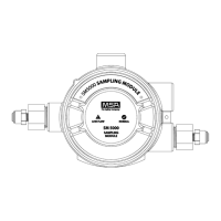
cylinder to the calibration inlet (see Fig. 1).
3.2.1 Zeroing with the
Pump Sampling Module
(3) Initiate the calibration procedure on the gas monitor (see gas monitor instruction manual).
(4) When the gas monitor indicates "APPLY ZERO GAS", press and hold the button by the calibration
inlet. Turn the knob on the regulator to permit the zero gas to flow. Simultaneously, the gas monitor will
make all corrections to the zero signal; there are no adjustments necessary.
(5) When the gas monitor is done zeroing, close the cylinder valve, release the button by the calibration
inlet, and quickly rotate the zero gas cylinder to remove the zero gas cylinder. Do not remove the tubing
from the flow controller.
(6) Locate and screw regulator into the cylinder.
NOTE: If unsure of which span gas to use or of the span gas value, consult your safety engineer or
officer or facility manager.

 Loading...