21
Calibration and Operation
US
SM5000 Sampling Module - DC Pump Model
3.2.2 Spanning with the Pump Sampling Module
(7) When calibrating, the span immediately follows the zero (see gas monitor instruction manual).
(8) When the gas monitor displays "APPLY SPAN GAS", press and hold the button by the calibration inlet.
Turn the regulator knob to permit the span gas to flow. The gas monitor will make all corrections to its
calibration; there are no adjustments necessary.
(9) When the gas monitor calibration is complete, release the button by the calibration inlet, close the
cylinder valve and remove the span gas cylinder.
(10) Unscrew the regulator from the gas cylinder and replace all calibration components in the kit.
(11) Return instrument receiving the signal from the gas monitor to normal run mode operation.
3.3 Operation
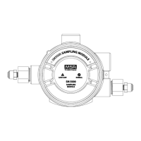
There are only two indicators on the front cover of the Pump Sampling Module which affect the operation of
the unit.
• The NORMAL indicator, the green LED, shows that there is power to the unit and the flow is greater than
.5 LPM.
• The LOW FLOW indicator, the red LED, indicates that the flow detector has insufficient gas flow for
proper monitoring. See chapter 4.3 "Troubleshooting Guidelines" for corrective action.
WARNING!
The pressure switch can fail and the orifice can clog if water enters the system. Always use the proper in-
line filter (P/N 10051406).

 Loading...