16
Installation
US
SM5000 Sampling Module - DC Pump Model
2.6 Electrical Connection
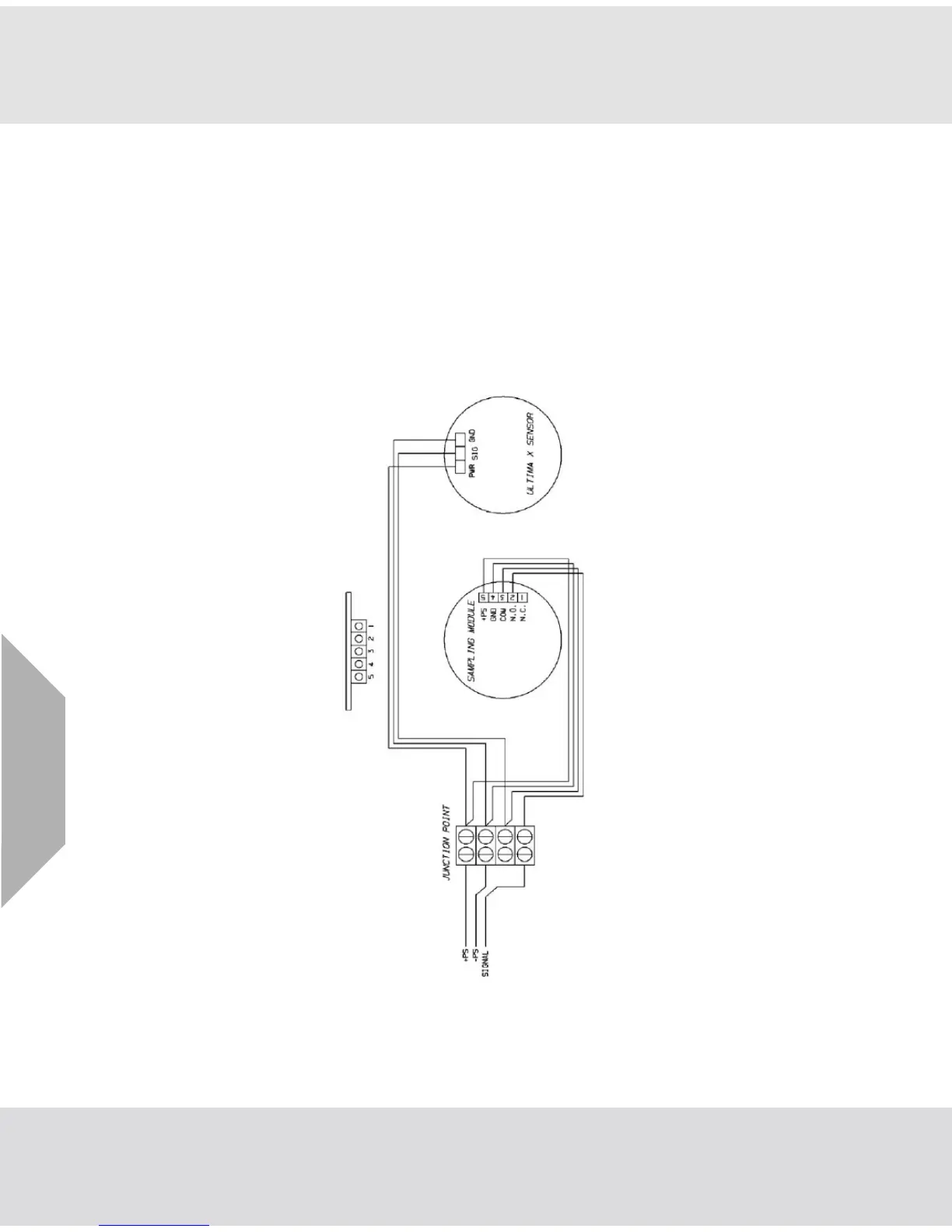
A flow detector within the Pump Sampling Module activates a relay when sufficient flow exists for proper
gas detection. Generally, the Ultima X5000 transmitter analog output signal can be routed through the
sampling module relay. When the flow is insufficient, the relay opens and the (AO) analog output signal is
interrupted. Equipment monitoring the AO can be configured to sound an alarm when the signal is inter-
rupted. See Fig. 5, Fig. 6 and Fig. 7 for a typical wiring schematic of the Sampling Module and Ultima X5000
Gas Monitor.
Other devices that alert when the flow loss relay activates can be connected to relay contact with the
Pump Sampling Module.
NOTE: The Pump Sampling Module utilizes a shielded four-conductor wiring harness. It is recommended
to use the shielded wire harness if installing the system where portable two-way radio, welding or large
machinery are located.
Fig. 5 Typical wiring - Ultima X