INSTALLATION INSTRUCTIONS
5
MSD • WWW.MSDPERFORMANCE.COM • (915) 857-5200 • FAX (915) 857-3344
PROGRAMMING
CYLINDER SELECT
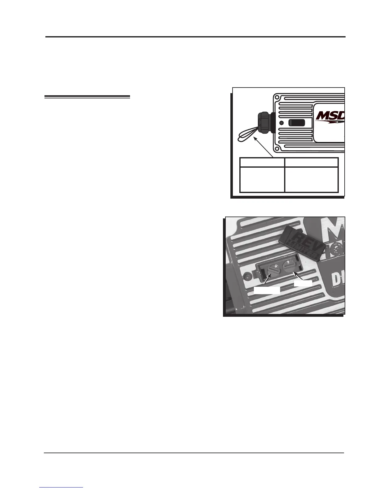
The MSD is programmed for operation on 8-cylinder engines.
If installing the Ignition on a different style engine, the number
of cylinders will need to be selected by cutting the cylinder
select wire loops as shown in Figure 1.
REV LIMITER
Routing Wires: The MSD wires should be routed away from direct heat sources such as exhaust
manifolds and headers and any sharp edges. The trigger wires should be routed separate from the
other wires and spark plug wires. It is best if they are routed along a ground plane such as the block
or rewall which creates an electrical shield. The magnetic pickup wires should always be routed
separately and should be twisted together to help reduce extraneous interference.
DIGIT
REV
LIMITER
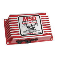
Figure 2 Adjusting the Rev Limits.
The rev limiter can be set from 2,000 to 11,000 rpm. To adjust
the rev limiter of the Digital 6AL, remove the black cover next
to the LED by prying up with the supplied screwdriver. The
dial on the left is for 1,000 rpm increments, on the right is for
100 rpm increments.
For a rev limiter in the 10,000 range, set the dials as they
would be for any other RPM but the left dial will use '0'.
To set the rev limiter to 11,000 rpm, put the left dial to '1'
and the right dial to '0'. Setting both rotary dials to '1' will
activate a special function explained below.
Note: The engine can be running as you make adjustments
to the rev limiter function.
REV LIMITER VERIFICATION
The MSD Digital 6AL has an optional built in Rev Limiter
Verication feature. When the key is in the On position (not
cranking or running), an rpm signal is sent to the tachometer
to verify the unit's rev limit setting. With this function users
can be sure of their rev limit settings before each drive.
This feature is not activated from the factory. To enable
this feature, follow the procedure below.
Note: It is important to note that this feature should not
be used with EFI systems. When activated, an rpm signal is sent to the tachometer. With an
aftermarket EFI system, this could activate the injectors causing a ooding situation.
Enable Rev Limit Verication
1. With the ignition switch in the off position, ground the Gray tach output wire.
2. With the Gray wire connected to ground, turn on power to the ignition without starting the engine.
3. Hold the Gray tach output wire to ground for seven seconds. (AT LEAST ve seconds.)
4. Release the wire from ground before ten seconds have passed.
5. To conrm the process has worked, cycle turn the key On. The tachometer should sweep to the
rpm limit set on the ignition.
As soon as this process is complete the feature will be activated. The Digital 6AL uses the red LED
to help indicate when an adequate amount of time has passed to release the Gray tach wire. The
LED will turn on after the wire has been grounded for ve seconds and will turn off at the 10 second
mark. To deactivate the feature again, repeat the same process.
CYLINDERS WIRE LOOPS
8 No Cut Loops
6 Cut One Loop
4 Cut Both Loops
1,000's
100's
Figure 1 Programming the Number of
Cylinders.