8
INSTALLATION INSTRUCTIONS
MSD • WWW.MSDPERFORMANCE.COM • (915) 857-5200 • FAX (915) 857-3344
ENGINE RUN-ON
If your engine continues to run even when the ignition
is turned Off you are experiencing engine Run-On. This
usually only occurs on older vehicles with an external
voltage regulator. Because the MSD receives power
directly from the battery, it does not require much current
to keep the unit energized. If you are experiencing run-on, it is
due to a small amount of voltage going through the charging
lamp indicator and feeding the small Red wire even if the key
is6turned off.
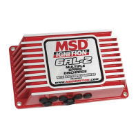
Early Ford and GM: To solve the Run-On problem, a Diode is supplied with the MSD in the parts
bag. By installing this Diode in-line of the wire that goes to the Charging indicator, the voltage is kept
from entering the MSD. Figure 6 shows the proper installation for early Ford and GM vehicles.
Note: Diodes are used to allow voltage to ow only one way. Make
sure the Diode is installed facing the proper direction (
as
shown in Figure 6
).
Ford: Install the Diode in-line to the wire going to the “1” terminal.
GM: Install the Diode in-line to the wire going to terminal #4.
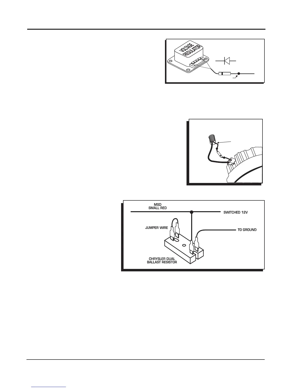
GM: 1973 - 1983 with Delcotron Alternators.
GM: Delcotron Alternators use an internal voltage regulator. Install
the Diode in-line on the smallest wire exiting the alternator (Figure
7). It is usually a Brown wire.
SMALLER OF THE 2-WIRES
DIODE
WIRE LOOM
GM 2-WIRE ALTERNATORS
Figure 7 Installing the Diode to a
1973-1983 GM Vehicle.
1A-100V DIODE
FORD VEHICLES
ATTACH DIODE TO TERMINAL "1"
EARLY GM VEHICLES
ATTACH DIODE TO TERMINAL "4"
TO
SPLICE HERE
1 2 3 4
Figure 6 Installing the diode to a GM or Ford Vehicle.
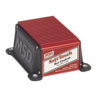
Most other applications: On
other applications where engine
Run-On is experienced, a
Resistor can be put in-line
to the MSD's small Red wire
(Figure 8). This resistor will keep
voltage from leaking through to
the MSD unit.
Figure 8 Wiring the Dual Ballast Resistor for Run-On.
MISSES AND INTERMITTENT PROBLEMS
Experience at the races has shown that if your engine is experiencing a miss or hesitation at higher
rpm, it is usually not directly ignition. Most probable causes include faulty wiring, a coil or plug wire
failure, arcing from the cap or boot plug to ground or spark ionization inside the cap. Several items
to inspect are:
• Always inspect the plug wires at the cap and at the plug for a tight connection and visually inspect
for cuts, abrasions or burns.
• Inspect the Primary Coil Wire connections. Because the MSD is a Capacitive Discharge ignition and
it receives a direct 12 volt source from the battery, there will not be any voltage at the Coil Positive (+)
terminal even with the key turned On. During cranking or while the engine is running, very high voltage
will be present and no test equipment should be connected.