EasyManua.ls Logo

MSI 694D Pro2 - User Manual

MSI 694D Pro2
99 pages
Print Icon
To Next Page IconTo Next Page
Loading...
Introduction
1-1
Chapter 1.
Introduction
The 694D Pro2 (MS-6321 v2.X) ATX mainboard is a high-performance
computer mainboard based on VIA
®
Apollo Pro133A chipset. The 694D
Pro2 is designed for Intel
®
Pentium
®
III (FC-PGA) processor for cost-
effective business/personal desktop and entry-level server markets.
The Apollo Pro133A consists of the VT82C694XDP North Bridge
and VT82C686B South Bridge. VT82C694XDP is a system controller sup-
porting AGP 4X, 133MHz Front Side Bus and eight banks of PC100/PC133
SDRAMs. With 133MHz Front Side Bus, the north bridge optimizes the
performance of Intel
®
Pentium III. The chipsets asynchronous bus design
is also ideal for CPU to run at FSB speeds of 66 and 100MHz.
The VIA
®
VT82C686B Super I/O PCI integrated Peripheral Controller
(PSIPC) includes PCI-to-ISA bridge controller, keyboard controller and USB
controller. In addition, it supports dual bus-master IDE with Ultra DMA 33/
66/100, four USB ports, system hardware monitoring and enhanced power
management capabilities.
This chapter includes the following topics:
Mainboard Specifications 1-2
Mainboard Layout 1-4
Quick Components Guide 1-5
Key Features 1-6
MSI Special Features 1-7
Question and Answer IconNeed help?

Do you have a question about the MSI 694D Pro2 and is the answer not in the manual?

Overview

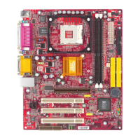
This document describes the 694D Pro2 (MS-6321 v2.X) ATX mainboard, a high-performance computer mainboard designed for Intel® Pentium® III (FC-PGA) processors, targeting cost-effective business/personal desktop and entry-level server markets.

Function Description

The 694D Pro2 mainboard is built around the VIA® Apollo Pro133A chipset, which comprises the VT82C694XDP North Bridge and VT82C686B South Bridge. This architecture supports dual Intel® Pentium® III (FC-PGA/FC-PGA2) processors, offering robust performance for its intended applications. The mainboard's asynchronous bus design allows the CPU to operate efficiently at various Front Side Bus (FSB) speeds, including 66MHz and 100MHz, while optimizing performance for 133MHz FSB with Intel® Pentium® III processors.

The VT82C694XDP North Bridge is a system controller that supports AGP 4X, a 133MHz Front Side Bus, and eight banks of PC100/PC133 SDRAMs. This enables high-speed graphics and memory access.

The VIA® VT82C686B Super I/O PCI integrated Peripheral Controller (PSIPC) South Bridge integrates several critical functions:

  • PCI-to-ISA bridge controller
  • Keyboard controller
  • USB controller
  • Dual bus-master IDE with Ultra DMA 33/66/100 support
  • Four USB ports
  • System hardware monitoring
  • Enhanced power management capabilities

Additionally, the mainboard can optionally include a 1394 PHY Controller (TI® TSB41LV02 PHY Digital-to-Analog Transceiver) supporting up to two 1394/1394A v2.0 compatible data channels, and a 1394 Link Layer Controller (TI® TSB12LV26 1394 Link Layer Host Controller) compatible with IEEE 1394, 1394 OHCI v1.0 & 1394A v2.0, supporting 100/200/400 Mbps high throughput and 3.3V & 5V operation for PCI-to-1394 interface.

Important Technical Specifications

CPU:

  • Supports dual Intel® Pentium® III (FC-PGA/FC-PGA2) processors.
  • Supports CPU speeds from 233MHz up to 1.13GHz (233MHz, 266MHz, 300MHz, 333MHz, 350MHz, 400MHz, 450MHz, 500MHz, 533MHz, 667MHz, 700MHz, 733MHz).

Chipset:

  • VIA® 694X chipset (510 BGA) with P-III FSB @133MHz, AGP 4X, PCI, and Advanced ECC Memory Controller. Supports PC100/133 SDRAM & VCM technology.
  • VIA® VT82C686B chipset (352 BGA) with Advanced Power Management Features and Dual bus Master IDE Ultra DMA 33/66/100.
  • Optional 1394 PHY Controller (TI® TSB41LV02) and 1394 Link Layer Controller (TI® TSB12LV26).

Clock Generator:

  • Supports 66.6MHz, 100MHz, and 133MHz clocks.

Main Memory:

  • Supports eight memory banks using four 168-pin unbuffered DIMM slots.
  • Maximum memory size of 2GB.
  • Pin outs support 8 banks up to 2GB DRAM (256MB DRAM Technology) at 100MHz.
  • Recommended limit of 3 DIMMs or 6 banks at 133MHz for 1.5GB maximum memory.
  • Supports ECC (1-bit Error Code Correct) function.
  • Supports 3.3V SDRAM DIMM.

Slots:

  • One AGP 4X (Accelerated Graphics Port) slot.
  • One CNR (Communication Network Riser) slot.
  • Five 32-bit Master PCI Bus slots.
  • Supports 3.3V/5V PCI bus Interface.

On-Board IDE:

  • An IDE controller on the VIA® VT82C686B chipset provides IDE HDD/CD-ROM with PIO, Bus Master, and Ultra DMA 66/100 operation modes.
  • Can connect up to four IDE devices.

Promise RAID (Optional):

  • Supports RAID 0 or 1.
  • Can connect up to four IDE HDDs (ATA33/66/100).

On-Board Peripherals:

  • One floppy port supporting 2 FDDs with 360K, 720K, 1.2M, 1.44M, and 2.88Mbytes.
  • Two serial ports (COM A + COM B).
  • One parallel port supporting SPP/EPP/ECP mode.
  • Four USB ports (2 Rear Connectors/ 2 from USB Front Pin Header -- one of the ports supports USB PC to PC Networking function).
  • One IrDA/HP connector for HPSIR.

BIOS:

  • AWARD® BIOS ROM with "Plug & Play" functionality, detecting peripheral devices and expansion cards automatically.
  • Desktop Management Interface (DMI) function for recording mainboard specifications.

Dimension:

  • ATX Form Factor: 25.4cm (W) x 30.4cm (L).
  • Nine mounting holes.

Usage Features

CPU Installation:

  • Supports installation of single or dual CPUs in Socket 370.
  • CPU installation involves pulling a lever, raising it to 90 degrees, aligning the gold arrow on the CPU with the lever's end, placing the CPU, and closing the lever.
  • Warning: Overheating can damage the CPU and system; ensure the cooling fan works properly.

Memory Installation:

  • Supports single-sided or double-sided 168-pin DIMMs.
  • DIMM slots have two Notch Keys ("VOLT" and "DRAM") to ensure correct orientation.
  • Insert DIMM vertically and push until plastic clips automatically close.

Power Supply:

  • Supports ATX power supply.
  • ATX 20-Pin Power Supply connector with instant power-on function.
  • Pinout details for the 20-pin ATX connector are provided (e.g., 3.3V, 5V, 12V, GND, PS_ON, PW_OK).

Back Panel Connectors:

  • Mouse (PS/2 mini DIN, 6-pin female).
  • Keyboard (PS/2 mini DIN, 6-pin female).
  • USB (UHCI Universal Serial Bus root, 8-pin header for two ports).
  • Parallel Port (25-pin female centronic for LPT).
  • Serial Port (two 9-pin male DIN connectors for COM A & COM B).

Internal Connectors:

  • Floppy Disk Drive Connector (FDD1): Standard floppy disk drive connector supporting various types (360K, 720K, 1.2M, 1.44M, 2.88M).
  • Hard Disk Connectors (IDE1 & IDE2): Two 40-pin connectors for up to four hard disk drives, CD-ROMs, or 120MB floppies. IDE1 is primary, IDE2 is secondary.
  • IDE RAID HDD Connectors (IDE3 & IDE4 - Optional): Two 40-pin connectors for RAID 0 (striping) and RAID 1 (mirroring).
  • Case Connector (JFP1): Connects to Power Switch, Reset Switch, Speaker, Power LED, and HDD LED on the case.
    • Power Switch: 2-pin push button.
    • Reset Switch: 2-pin for system reboot.
    • Power LED: Supports 2-pin single color (Green for Full-On, blinks for suspend/sleep) or 3-pin dual color (Green for Full-On, Orange for suspend/sleep).
    • HDD LED: Shows hard disk activity.
  • Power Saving LED Connector (JGL1): For 3-pin or 2-pin (ACPI request) LEDs. Green for system on, orange for sleep state.
  • Remote Power On/Off Switch Connector (JRMS1): Connects to a 2-pin push button switch to turn the system on/off or enter sleep/suspend state.
  • Power Saving Switch Connector (JGS1): Attaches a power saving switch to enter sleep/suspend state or wake up the system.
  • Wake On Ring Connector (JMDM1): Connects to a modem card to power up the system upon receiving a signal.
  • Wake On LAN Connector (JWOL1): Connects to a LAN card to wake up the computer remotely.
  • IrDA Infrared Module Connector (J3): Connects to an IrDA Infrared module; requires BIOS setup configuration.
  • IDE RAID HDD LED Connector (J6): Connects to an HDD LED for IDE 3 or IDE4 activity.
  • Fan Power Connectors (CPUFAN1/CPUFAN2/SYSFAN): Three-pin connectors for CPU and system fans. Red wire is +12V, black wire is Ground.
  • USB PC To PC Connector (USB2): One USB (Universal Serial Bus) pin header for optional USB ports, supporting USB PC to PC Networking.
  • D-Bracket™ Connector (JP1 - Optional): A USB Bracket with four LEDs that indicate system problems through 16 signal combinations.
  • IEEE 1394 Connectors (J11 & J12 - Optional): Two 1394 pin headers for optional IEEE 1394 ports.

BIOS Setup Utility:

  • Accessed by pressing during POST.
  • Control Keys: Navigation (arrows), selection (Enter), exit (Esc), value change (+/-), help (F1), restore CMOS (F5), load fail-safe defaults (F6), load optimized defaults (F7), save & exit (F10).
  • Main Menu: Standard CMOS Features, Advanced BIOS Features, Advanced Chipset Features, Integrated Peripherals, Power Management Setup, PnP/PCI Configurations, PC Health Status, Frequency/Voltage Control, Load Fail-Safe/Optimized Defaults, Set Supervisor/User Password, Save & Exit Setup, Exit Without Saving.
  • Standard CMOS Features: Set date, time, floppy drive types, video adapter type, and halt on error conditions.
  • Advanced BIOS Features: Configure virus warning, CPU internal/external cache, processor number feature, quick power on self test, ATA/100 & SCSI boot order, first/second/third boot device, boot other device, swap floppy drive, boot up floppy seek, boot up NumLock status, Gate A20 option, typematic rate setting, typematic delay, security option, MPS version control, OS select for DRAM>64MB, video BIOS shadow, and various memory shadows.
  • Advanced Chipset Features: Configure DRAM cycle length, DRAM clock, memory hole, P2C/C2P concurrency, fast R-W turn around, system BIOS cacheable, video RAM cacheable, AGP aperture size, AGP-4X mode, AGP driving control/value, AGP fast write, OnChip USB, USB keyboard/mouse support, OnChip sound, OnChip modem, CPU to PCI write buffer, PCI dynamic bursting, PCI Master 0 WS write, PCI delay transaction, PCI #2 access #1 retry, AGP Master 1 WS write/read, memory parity/ECC check.
  • Integrated Peripherals: Configure OnChip IDE channels, IDE prefetch mode, PIO modes, UDMA modes, Init Display First, IDE HDD block mode, Onboard FDD controller, Onboard serial ports, UART 2 mode, IR function duplex, TX/RX inverting enable, Onboard parallel port, parallel mode, ECP mode use DMA, parallel port EPP type.
  • Power Management Setup: Configure ACPI function, power management (Min/Max Saving, User Define), HDD power down, doze mode, suspend mode, PM control by APM, video off option/method, modem use IRQ, and wake up events (VGA, LPT & COM, HDD & FDD, PCI Master, PowerOn by PCI Card, Wake Up On LAN/Ring, RTC Alarm Resume, Primary INTR, IRQs Activity Monitoring).
  • PnP/PCI Configurations: Configure PnP OS installed, reset configuration data, resources controlled by, IRQ/DMA resources, PCI/VGA palette snoop, assign IRQ for VGA/USB, INT pin assignments.
  • PC Health Status: Monitor CPU temperature, CPU fan speed, Vcore, and other voltages.
  • Frequency/Voltage Control: Auto detect DIMM/PCI clock, CPU host clock (CPU/PCI), CPU1/2 clock ratio, CPU1/2 Vcore select.
  • Password Protection: Set Supervisor and User passwords for BIOS access. Supervisor can change settings, User can only view.

Driver Installation:

  • Detailed steps for installing VIA® Chipset Drivers for Windows® 98SE, 2000, ME, and NT4.0.
  • Includes installation of VIA Atapi Vendor Support Driver, AGP VxD Driver, IRQ Routing Miniport Driver, and VIA INF Driver.
  • One Touch Setup: Available for Windows® ME and 2000 to install multiple drivers automatically.

USB PC to PC Networking Function:

  • Allows building a local area network without a network adapter by connecting multiple PCs via USB PC to PC port.
  • Supports TCP/IP, NetBEUI, and IPX protocols for sharing resources and Internet access.
  • Installation: Install GeneLink™ LAN Driver, connect PCs via USB PC to PC cable, network login, share resources, and connect to the Internet.
  • Internet Connection Sharing: Setup "Internet Connection Sharing" on all connected computers via USB PC to PC cables.

Maintenance Features

Clear CMOS Jumper (JBAT1):

  • Allows clearing CMOS data (system configuration) by shorting pins 2-3 while the system is off, then returning to pins 1-2.
  • Warning: Do not clear CMOS while the system is on to avoid damaging the mainboard.

T.O.P Tech™:

  • An extended sensing device that accurately detects CPU temperature.
  • Temperature information is available in the BIOS setup menu and via PC Alert™ software.

PC Alert™ III:

  • A utility found on the CD-ROM disk that monitors hardware status in real-time.
  • Monitors CPU & system temperatures, fan speeds, system voltages, and chassis intrusion.
  • Provides warnings if any item is abnormal, highlighting it in red and disabling the warning until the user acknowledges it.
  • Features: Network Management (monitoring & remote control), Basic System Utilities (Scandisk & Defragment), 3D Graphics Design (friendly user interface), Software Utilities (SoftCooler Optimized Cooling).

D-LED™ & D-Bracket™:

  • D-LED™ consists of four LEDs embedded in the mainboard that provide diagnostic signals for system problems (VGA, RAM, or other failures).
  • D-Bracket™ is an optional USB Bracket integrating four LEDs with similar functions to D-LED™, allowing users to identify system problems through 16 various combinations of LED signals.
  • A table of D-LED/D-Bracket signals and their corresponding descriptions is provided for troubleshooting (e.g., System Power ON, Early Chipset Initialization, Memory Detection Test, Decompressing BIOS image, Initializing Keyboard Controller, Testing VGA BIOS, Processor Initialization, Testing RTC, Initializing Video Interface, BIOS Sign On, Testing Base and Extended Memory, Assign Resources to all ISA, Initializing Hard Drive Controller, Initializing Floppy Drive Controller, Boot Attempt, Operating System Booting).

BIOS Default Settings:

  • Load Fail-Safe Defaults: Loads BIOS default values for minimal/stable system performance.
  • Load Optimized Defaults: Loads factory settings for optimal system performance.

Password Management:

  • Allows setting Supervisor and User passwords to prevent unauthorized access to BIOS settings.
  • The Security Option in Advanced BIOS Features determines when the password prompt appears (at boot and/or at Setup entry).

MSI 694D Pro2 Specifications

General IconGeneral
BrandMSI
Model694D Pro2
CategoryMotherboard
LanguageEnglish

Related product manuals