2-18
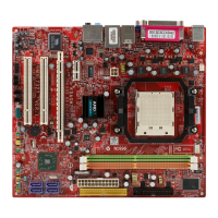
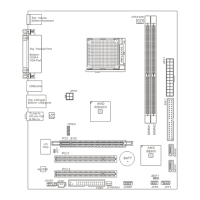
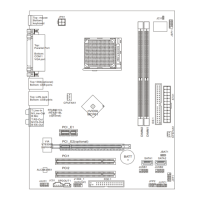
MS-7327 Mainboard
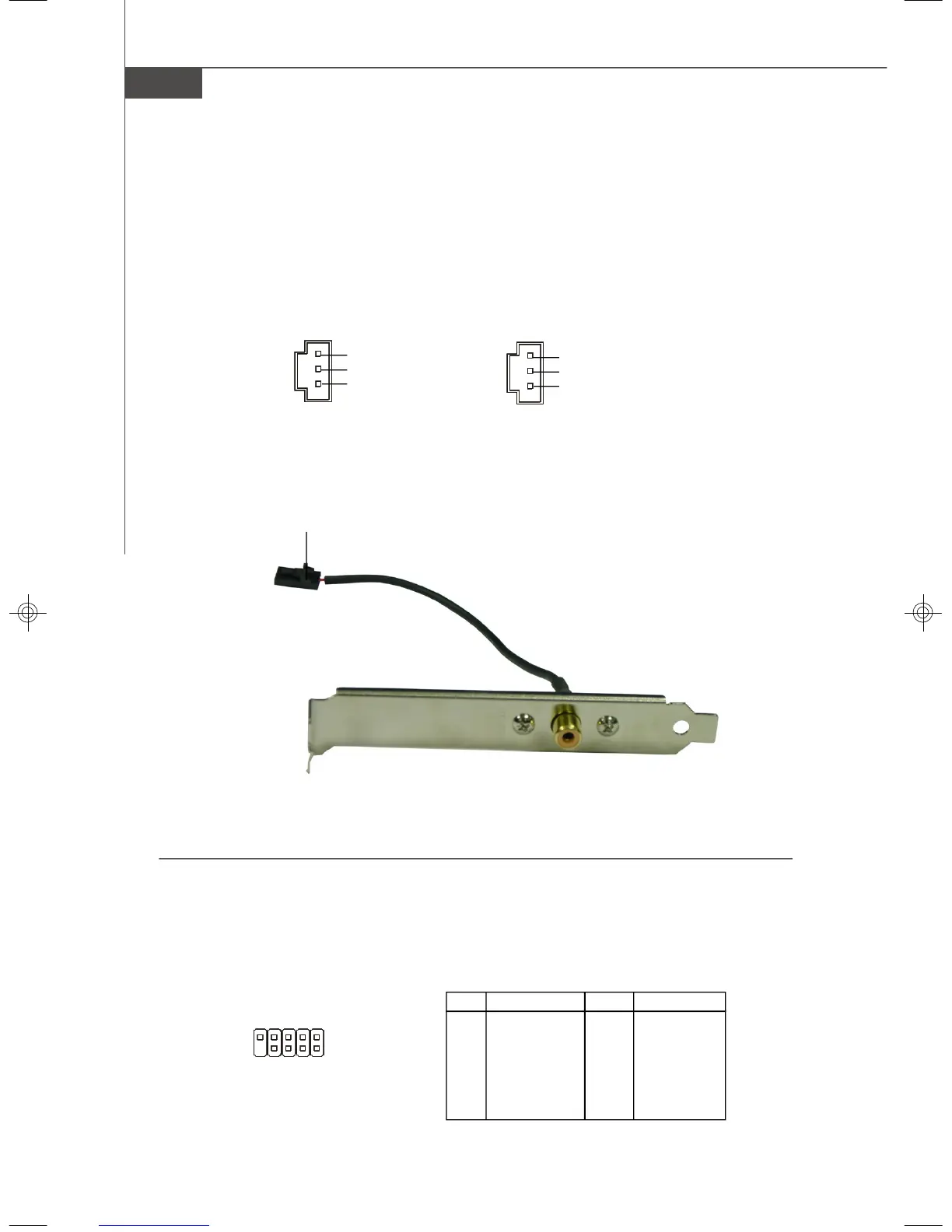
Connected to SPDOUT1 / SPDIN1
SPDIF Bracket (Optional)
SPDIF-Out / SPDIF-In Connector: SPDOUT1 / SPDIN1 (Optional)
This connector is used to connect SPDIF (Sony & Philips Digital Interconnect Format)
interface for digital audio transmission.
SPDOUT1
GND
SPDIF OUT
VCC
SPDIN1
GND
SPDIF IN
VCC
JSPI Debugging Pin Header: JSPI1
The pin header is for internal debugging only.
JSPI1 Pin Definition
PIN SIGNAL PIN SIGNAL
1 VCC3_SB 2 VCC3_SB
3 SPI_MISO 4 SPI_MOSI_F
5 SPI_CSO_F# 6 SPI_CLK_F
7 GND 8 GND
9 Reserved 10 NC
JSPI1
9
10
2
1
7327v1.0-2.p65 2007/4/13, 上午 10:4018