2-9
Hardware Setup
Power Supply
The mainboard supports ATX power supply for the power system. Be-
fore inserting the power supply connector, always make sure that all compo-
nents are installed properly to ensure that no damage will be caused.
PIN SIGNAL
1 GND
2 GND
3 12V
4 12V
JPW1 Pin Definition
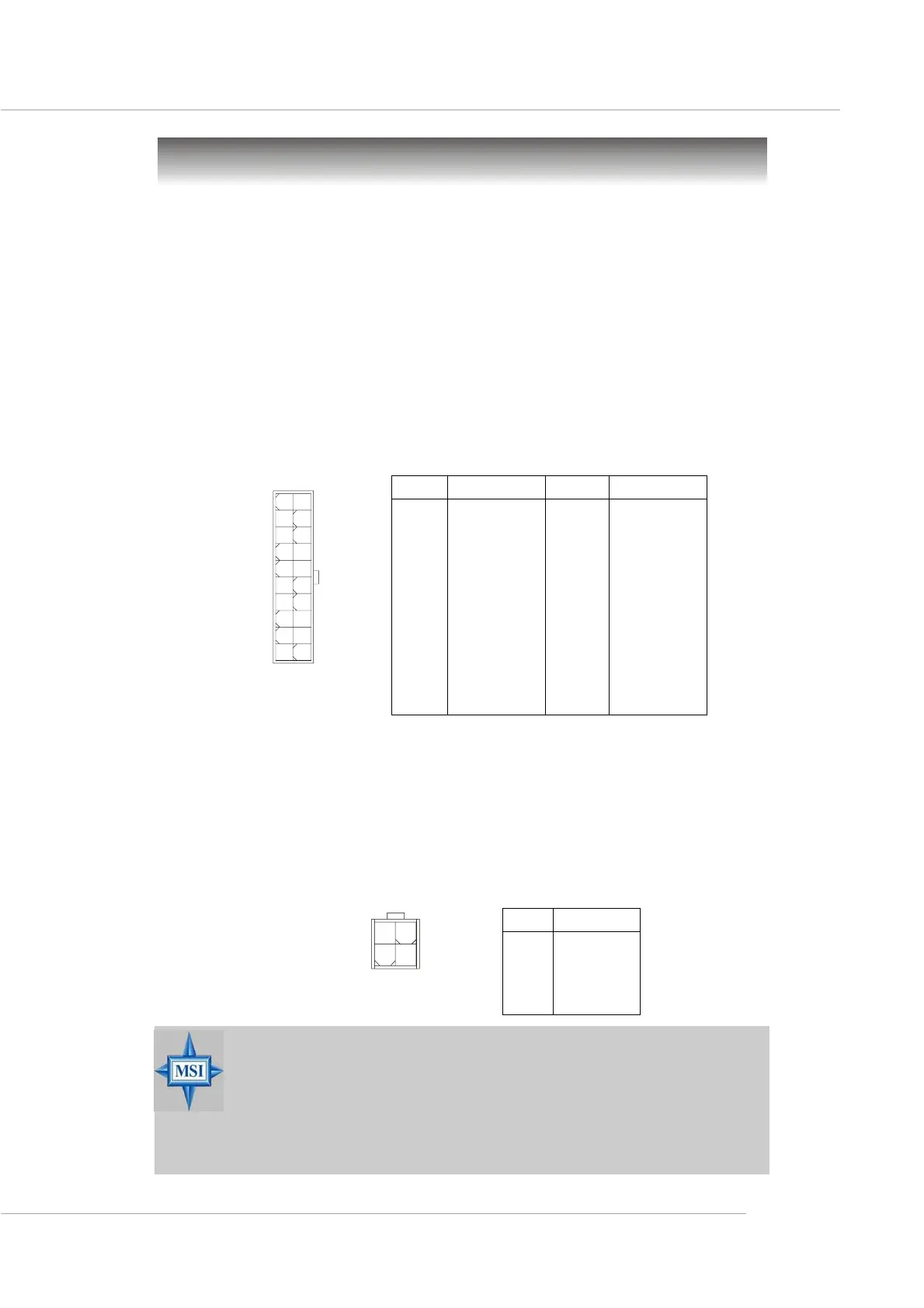
ATX 20-Pin Power Connector: CONN1
This connector allows you to connect to an ATX power supply. To
connect to the ATX power supply, make sure the plug of the power supply is
inserted in the proper orientation and the pins are aligned. Then push down the
power supply firmly into the connector. The power connector supports in-
stant power on function which means that system will boot up immediately
when the power supply connector is inserted on the board.
JPW1
1
34
2
MSI Reminds You...
1. These two connectors connect to the ATX power supply and
have to work together to ensure stable operation of the
mainboard.
2. Power supply of 350 watts (and above) is highly recommended
for system stability.
10
1
20
11
PIN SIGNAL
11 3.3V
12 -12V
13 GND
14 PS_ON
15 GND
16 GND
17 GND
18 -5V
19 5V
20 5V
PIN SIGNAL
1 3.3V
2 3.3V
3 GND
45V
5 GND
65V
7 GND
8 PW_OK
9 5V_SB
10 12V
CONN1 Pin Definition
ATX 12V Power Connector: JPW1
This 12V power connector is used to provide power to the CPU.
CONN1
 Loading...