MTD Engine - Series 350/450/650
24
8.14. Note or mark the orientation of the plate.
Notches in the plate allow air to reach emulsion
ports: one for the main jet and one for the pilot
jet. Channels in the rubber provide air passage
to the choke-side bowl vent.
CAUTION: When working around the fuel sys-
tem, do not bring any sources of heat, spark, or
open flame close enough to the work are to pose
a fire hazard.
• Drain the fuel tank or clamp the fuel line before
starting work to prevent spillage.
• Dispose of drained fuel in a safe and responsible
manner.
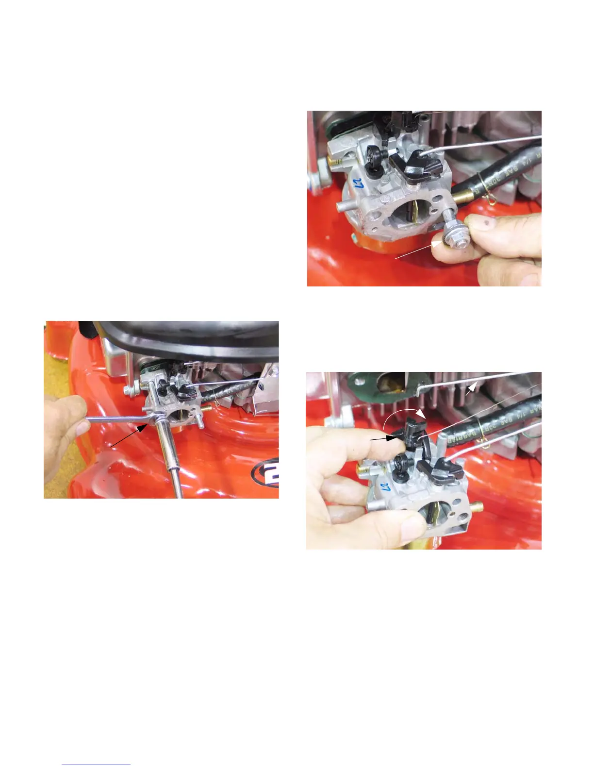
8.15. To remove the carburetor, disconnect the fuel
line.
8.16. Double-nut the studs for removal, with a washer
between the nuts serrated faces of the nuts.
See Figure 8.16.
NOTE: There are differences between the link-
ages on the Series 650 carburetor, and those
shared by the Series 350 and Series 450.
Removal technique is similar.
8.17. After the second stud is removed, the carburetor
can be maneuvered to disconnect the linkages.
See Figure 8.17.
8.18. Rotate the throttle arm until it meets the idle
speed screw, then pivot the carburetor slightly to
disengage the 90 degree bend at the end of the
governor rod. See Figure 8.18.
Figure 8.16
Stud removal:
double-nut method
Figure 8.17
Note: washer between nuts
Figure 8.18
Throttle arm
Governor rod
www.mymowerparts.com
For Discount White Outdoor Parts Call 606-678-9623 or 606-561-4983
 Loading...