MTD Engine - Series 350/450/650
25
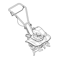
8.19. Pivot the carburetor to disengage the Z-fitting on
the end of the choke rod. See Figure 8.19.
8.20. Unhook the stabilizer spring that takes-up the
play between the governor arm, the governor
rod, and the throttle arm on the carburetor.
NOTE: The carburetors used on all three
engines are similar in design, but differ in cali-
bration.
NOTE: The jet markings may be used for identi-
fication purposes, but the technician should not
attempt to infer orifice sizes from the identifica-
tion numbers.
NOTE: Installing the wrong main jet, or a carbu-
retor with the wrong main jet will produce perfor-
mance and emissions issues.
Figure 8.19
Choke rod
Choke arm
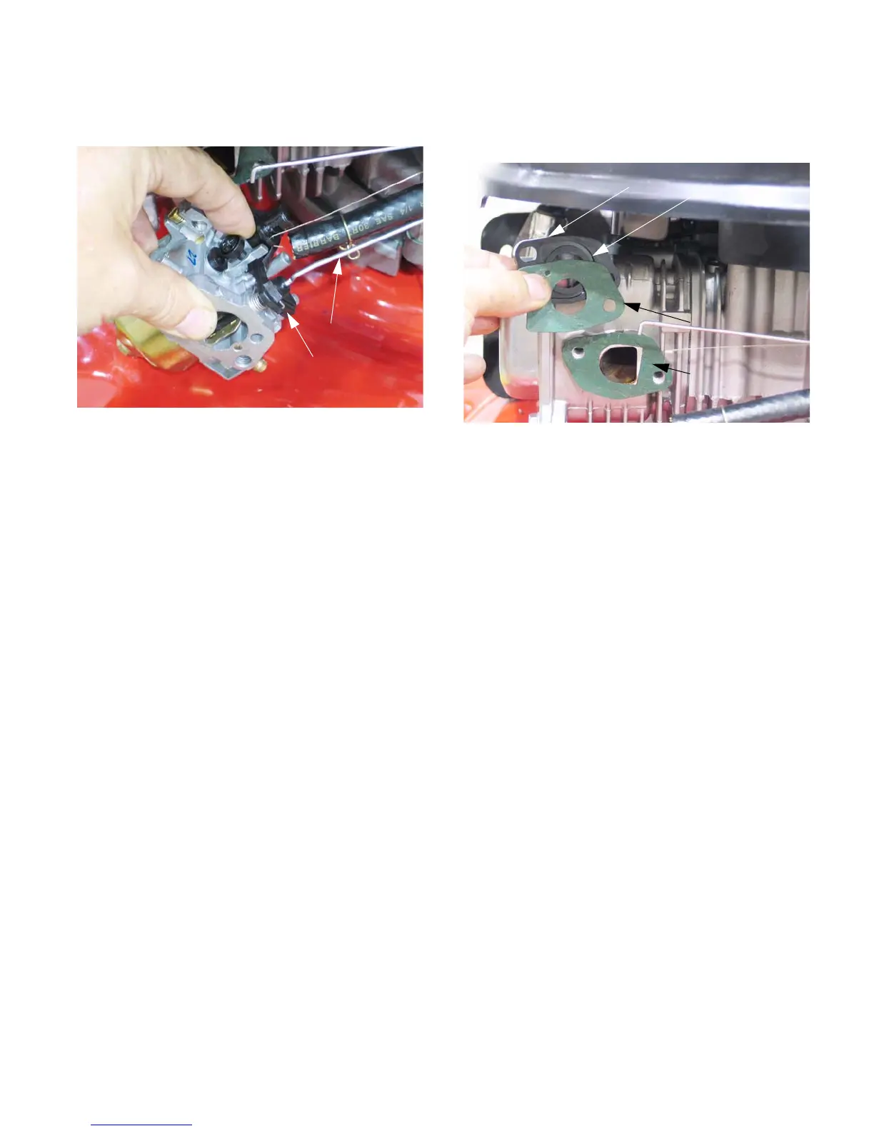
8.21. Between the carburetor and the cylinder head is
an insulator, sandwiched between two gaskets.
See Figure 8.21.
NOTE: The gaskets are different, and there is an
orientation to the insulator.
• The gasket with the “D” shaped opening goes
between the insulator and the cylinder head,
matching the shape of the gasket to the shape of
the intake port.
• The bowl vent channel in the insulator faces the
carburetor, with the exit toward the bottom.
• There is a small hole in the insulator to carbure-
tor gasket. The hole should be aligned to allow
passage of air through the bowl vent channel to
the throttle side bowl vent in the carburetor body.
Figure 8.21
Gasket: insulator
to cylinder head
Gasket: Insulator
to carburetor
Insulator
Bowl vent channel
www.mymowerparts.com
For Discount White Outdoor Parts Call 606-678-9623 or 606-561-4983
 Loading...