AC Line / Load Reactors
User Manual
Data subject to change without notice 29 of 32 INSTR-011 REL. 150109 REV.006
See www.mtecorp.com for current data and CAD drawings
Typical Connection Diagrams
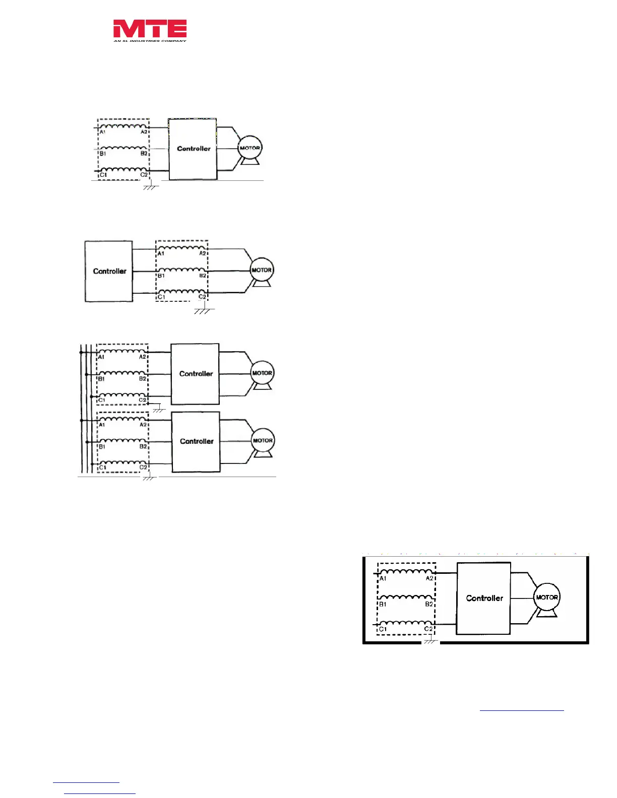
Figure 5. Single Phase connection diagram.
Standard three phase reactors may be used for single phase applications. Refer to application note
AN0102 for proper selection. Application Notes are available on our website at www.mtecorp.com.
Fig 4a LINE Reactor
Connects between power source and VFD
Fig. 4b LOAD Reactor
Connects between ASD and load (motor)
Fig 4c Use individual Line Reactors for
independent start/ stop drives connected to a
common power source. If inverters are slaved
and will always run together a single reactor
sized for total motor current may be used.