I 15 I
4.4.1 Mounting distances
Active measuring range
The technical data of each sensor is checked as well as documented
and the active stroke length (useful electrical stroke) with its start
and end position is adjusted during final inspection and testing
(see Fig. 22).
NOTICE
On all sensors, the areas left and right of the active stroke length
are provided for mounting and damping of the measuring signal.
They should not be used for measurement, but the active stroke
length can be exceeded without problem.
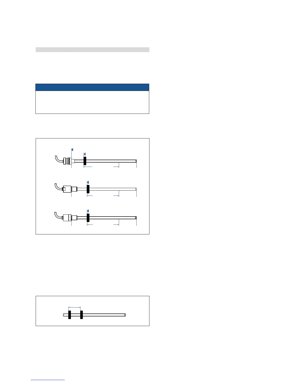
Mechanical zero
To ensure that the entire measuring range can be used electrically,
the position magnet must be mounted mechanically as follows:
63.5 / 66
(2.5 / 2.6)
51
(2)
Start position
Start position
Start position
RD4 type »S«
RD4 type »M«
RD4 type »C«
Reference edge of mounting
Stroke length
Stroke length
Stroke length
63.5
(2.5)
21.4
(0.84)
51
(2)
63.5 / 66
(2.5 / 2.6)
minimum 75 (3)
Mounting ring manget
Mount the magnetic with the non-magnetic material for mounting,
screws, spacers, etc..
– Max. permissible surface pressure: 40 N/mm
2
– Max. fastening torque for M4 screws: 1 Nm; use washers, if necessary
Multi-position measurement
The minimum distance between the magnets is 75 mm (3 in.)
Fig. 22: Mechanical zero
Fig. 23: Minimum distance for multi position measurement
Controlling design dimensions are always in metric units and measurements in ( ) are in inches

 Loading...


