(1.06)
22.9
(0.9)
12.7
(0.5)
4.4
(0.17)
10
(0.39)
5.8
(0.23)
Ø 22.9
(Ø 0.9)
45°
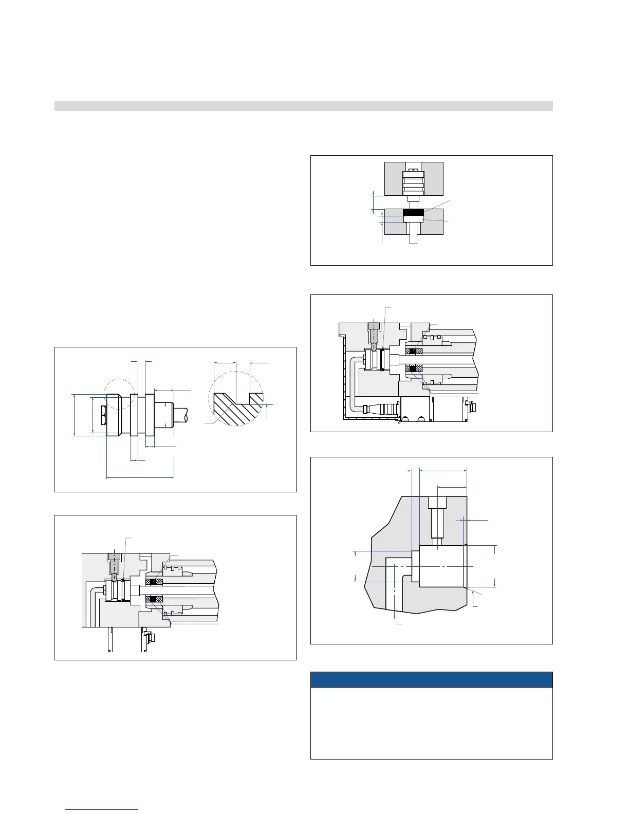
4.4.2 Installation of RD4 with pressure t ange »S«
Cylinder mounting
For installation in fluid power cylinders, the standard sensor system
consists of the rod and the mounting flange, and the B type electron-
ics. Install the rod using the fit and seal it off by means of the O-ring
and the supporting ring. Block the rod using a shoulder screw. The
adaptor plate of the separate electronics housing facilitates mounting
on the outside of small cylinders. Advantage of this version: Connec-
tion to the measuring rod is via the bottom of the housing. Thus the
sensor system is fully encapsulated and protected against external dis-
turbances.
Note for cylinder installation:
– The position magnet should not grind on the measuring rod.
– The bore in the piston rod is dependent on the hydraulic pressure
and the piston’s velocity. The minimum drilling should be 13 mm
(0.52 in.).
– Do not exceed the peak pressure.
– Protect the measuring rod against wear.
NOTICE
To fulfill the EMC standards for emission and immunity the
following points are necessary:
• The sensor electronics housing has to be connected to machine
ground.
• The cable between the sensor and the electronics must be
integrated into a metallic housing.
O-ring 21.9 × 2.6 (no. 560 705)
Back-up ring (no. 560 629)
Position magnet
Non-magnetic
material
32
(1.26)
5
(0.2)
20.32
(0.8)
20
(0.79)
Bore
27 H7
(1.07)
75°
(3)
2.54
(0.1)
Ø 10…20 (Ø 0.39...0.79)
bore for cable to electronic housing
Fig. 24: Pressure fit flange details
Fig. 25: Mounting example Pressure fit flange »S« and sensor electronics with bottom
cable entry
Fig. 26: Minimum installation dimensions for magnetic material
Fig. 27: Mounting example Pressure fit flange »S« and sensor electronics with side cable
Fig. 28: Mounting detail: Setscrew 8 M6 - ISO 7379 with internal hexagon
Controlling design dimensions are always in metric units and measurements in ( ) are in inches

 Loading...


