I 17 I
4.4.3 Installation of RD4 with threaded ange »M« & »T«
Rod
The sensor’s pipe will be fixed via the threaded flange M18×1.5 or
3/4”-16 UNF.
Mounting should be with non-magnetic material. If using magnetic
material necessarily follow the displayed installation dimensions.
Cylinder mounting
– The position magnet should not grind over the measuring rod.
– The bore in the piston rod is dependent on the hydraulic pressure
and the piston’s velocity. The minimum drilling should be 12 mm
(0.5 in.).
– Do not exceed the peak pressure.
– Protect the measuring rod against wear
– Pressure sealing is defined by cylinder manufacturer
Mounting example threaded ange »M«
Sealing results from the provided O-ring mounted in the undercut.
AF23
Screw thread
< 50 Nm
O-ring
Alternative screwing bore
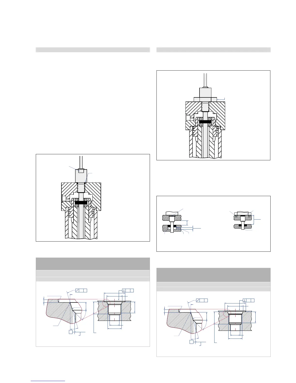
4.4.4 Installation of RD4 with threaded ange »C« & »D«
The sensor’s pipe will be fixed via the threaded flange M18×1.5 or
3/4”-16 UNF.
AF46
Screw thread
< 50 Nm
Position magnet
For accurate position measurement mount the magnet with
non-magnetic fastening material (screws, supports etc.).
Fig. 29: Mounting example for threaded flange
Fig. 30: Alternative screwing bore: Threaded flange M18×1.5 based on DIN ISO 6149-1
Fig. 31: Mounting example for threaded flange »C«
Fig. 32: Installation with non-magnetic & magnetic material
Fig. 33: Alternative screwing bore: Threaded flange M18×1.5 based on DIN ISO 6149-1
Controlling design dimensions are always in metric units and measurements in ( ) are in
inches
Thread
(d
1
×P)
d
2
d
3
d
4
d
5
L
1
L
2
L
3
L
4
Z°
M18×1.5 55 mm 13 mm 24.5 mm 19.8 mm 2.4 mm 28.5 mm 2 mm 26 mm 15°
3/4x16 See Appendix B
This dimension applies
when tap drill cannot
pass through entire boss
Thread (d
1
×P)
(Reference size)
Applies at Ød
4
A
R 0.4 max.

 Loading...


