Temposonics
®
R-Series EtherNet/IP
TM
Operation Manual
I 18 I
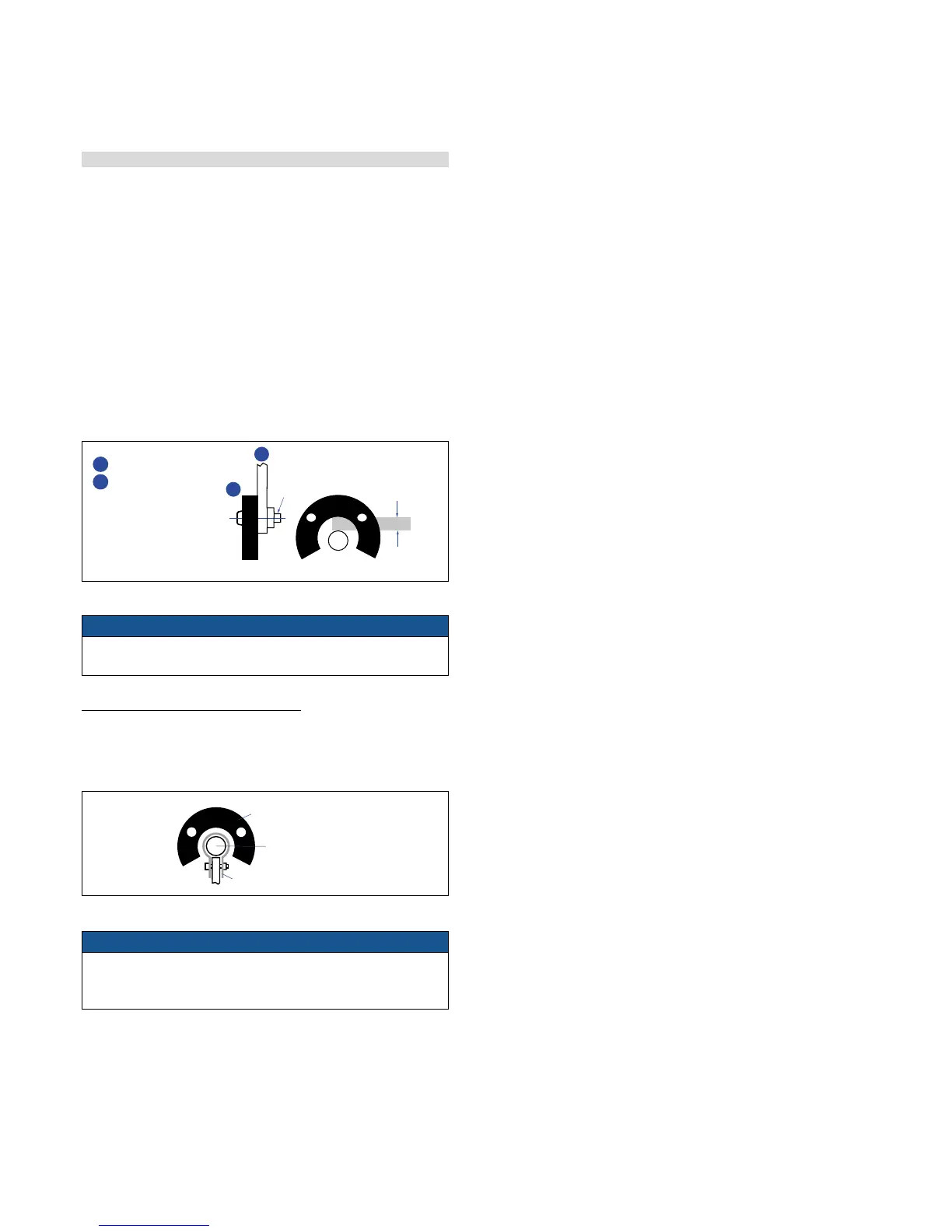
Fig. 34: Mounting device for U-magnet
Large stroke lengths from 1 meter (39 in.)
Horizontally installed sensors should be supported mechanically at the
rod end. Longer rods require evenly distributed mechanical support over
the entire length. In this case an U-magnet (see fig. 35) is used for
NOTICE
A maximum permissible air gap of 3 ±1 mm (0.12 in.) must not be
exceeded.
NOTICE
Use the electronics and sensor rod with the same serial number
together! For further information contact the application
engineering team.
Fig. 35: Example of sensor support
SW 46
Anziehmoment
≤ 50 Nm
> 30
Magnet
Empfohlene
Hydraulik-
abdichtung
Abb. 10
Einbau mit unmagnetischem Material
Magnet
nicht-magnetisbare
Distanzscheibe
> 15
min. 5
Abb. 11
Einbau mit magnetisierbarem Material
Abb. 12
Beispiel Sensorunterstützung
Alternative
Hydraulikdichtung
O-Ring 15,3 x 2,2
Sensor-Druckgehäuse
Stab mir Flansch
bleibt im Zylinder
Ringmagnet
Basissensor
Elektronikkopf mit Messeelement
austauschbar über zwei M4 Schrauben
mit 2,5 mm Innensechkant,
Anziehmoment max. 1,3 Nm
U-magnet
Sensor rod
Non-magnetic retaining clip
4.4.4 Magnet installation
Mounting the ring magnet
Install the magnet using non-magnetizable material for mounting
device, screws, spacers etc.
– Max. permissible surface pressure: 40 N/mm
2
– Max. fastening torque for M4 screws: 1 Nm; use washers,
if necessary
Mounting the U-magnet
Using a non-magnetizable mounting device is mandatory. The magnet
must not rub against the measuring rod. Alignment errors are
compensated via the air gap.
– Max. surface pressure: 40 N/mm
2
– Max. fastening torque for M4 screws: 1 Nm;
use washer, if necessary
Controlling design dimensions are always in metric units and measurements in ( ) are in inches
3 ±1
(0.12 ± 0.04)
M4
2
1
U-magnet
2
Non-magnetic
mounting device

 Loading...


