11
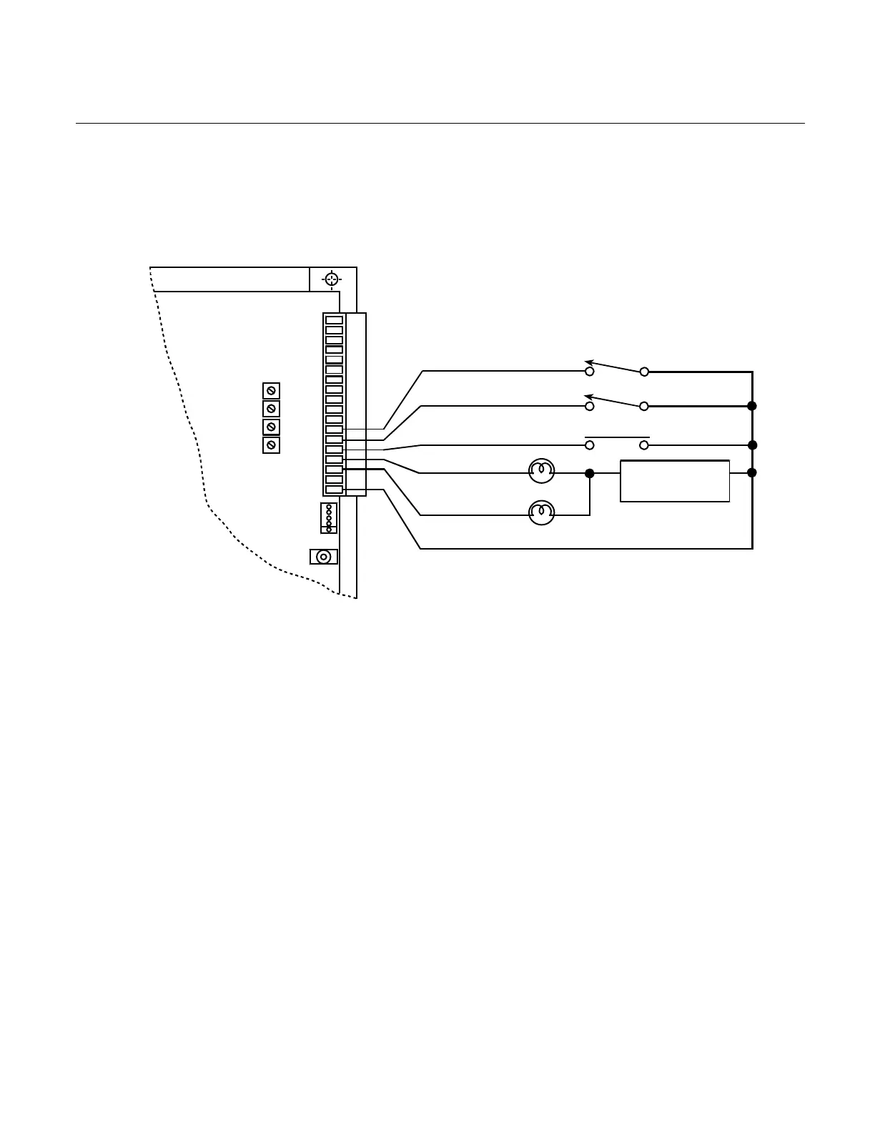
I/O Wiring and Descriptions
The amplifier has three inputs and two outputs. These inputs and outputs are designed to
interface to a 24-volt logic system. The amplifier is shipped so that the operation of the inputs
are as follows.
With no wires connected to VEL/TORQUE, ENABLE, or START, the amplifier is disabled and
normal operation will not occur. The inputs are activated by connecting them with a switch
closure to any of the provided GND terminals.
TB1
1
18
SIG
BAL
RESP
CUR
24 VDC
SUPPLY
+
–
18
16
15
14
13
12
FAULT
READY
START
ENABLE
DISABLE
TORQUE
VELOCITY
The actual decision as to open or closed switches occurs at a voltage level between 5-8 volts
dc. Less than 5 volts is active; greater than 8 volts is inactive.
The VEL/TORQUE Input determines the drive mode. When the switch is open, the Velocity
mode is selected. When the switch is closed, the Torque mode is selected.
The ENABLE Input must be on to enable the drive.
The START Input (option only) can be used by the personality interface option as a way to
start motion.
The FAULT Output will come on when a fault condition occurs. This is equivalent to an open
collector NPN transistor whose emitter is connected to GND.
The READY Output (option only) can be turned on or off by the computer interface option.