13
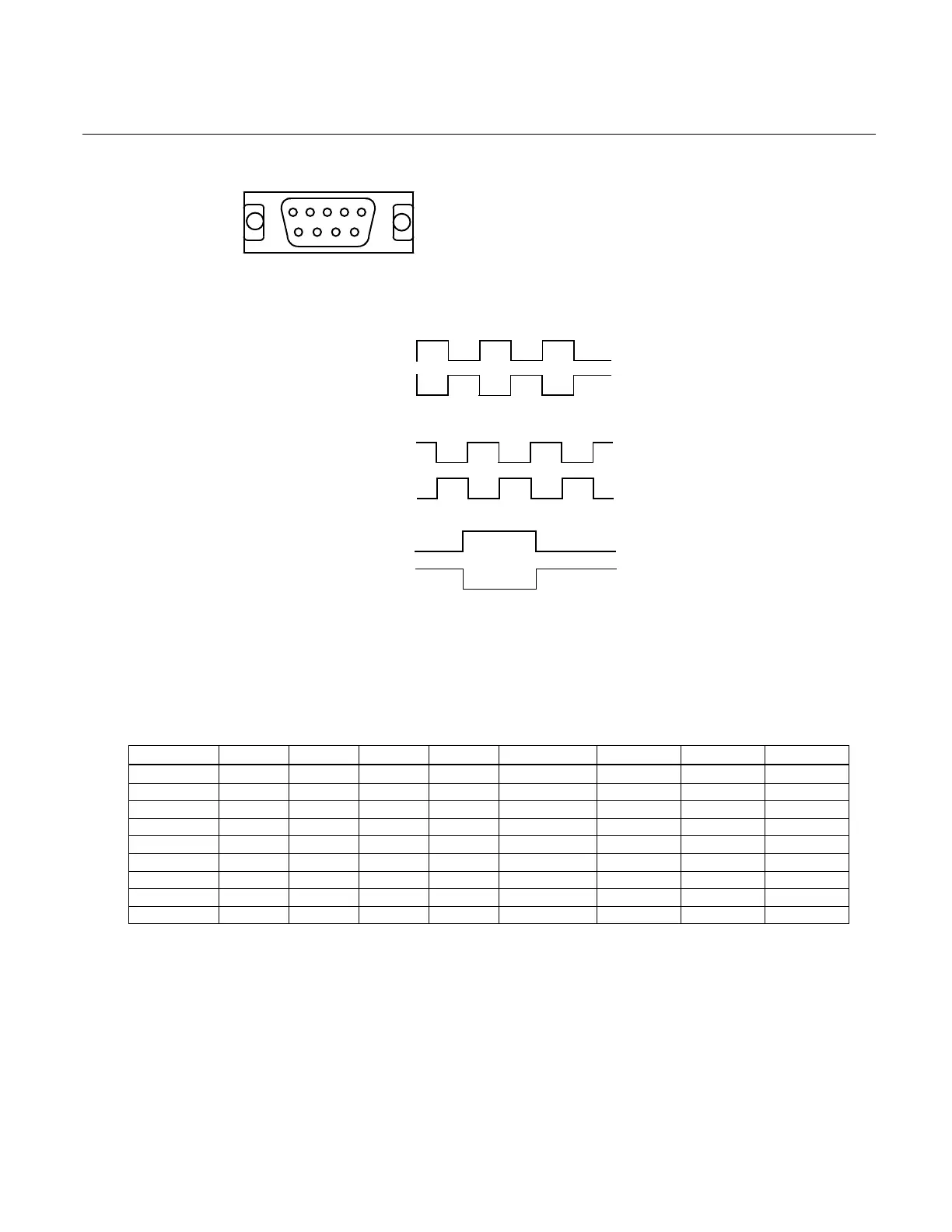
Simulated Encoder Connector
9 8 7 6
5 4 3 2 1
PIN 1 = A\ PIN 6 = A
PIN 2 = B PIN 7 = B\
PIN 3 = M PIN 8 = M\
PIN 4 = GND PIN 9 = GND
PIN 5 = SHIELD
The phase relationship of channels A, B and M for CW rotation:
1 A\
6 A
2 B
7 B\
3 M
8 M\
The marker pulse is about .5 degrees in width. The above illustration is for 1024 line condition
(default).
The above signals are TTL differential outputs from a DS26LS31 differential driver. The logic
0 is typically between 0 and .5 volts and logic 1's are typically between 3.3 and 4 volts.
SW1 is provided as a means to determine the resolution of the simulated encoder signals.
SW1 1 2 3 4 LINES 12 BIT 14 BIT MARK
ON ON ON ON 2000 NO YES YES
OFF ON ON ON 500 YES YES YES
ON OFF ON ON 400 YES YES YES
(Default) OFF OFF ON ON 1024 YES YES YES
ON ON OFF ON 250 YES YES YES
OFF ON OFF ON 1000 YES YES YES
ON OFF OFF ON 720 YES YES YES
OFF OFF OFF ON 360 YES YES YES
OFF OFF OFF OFF 4096 NO YES NO
The normal factory configuration of 2-Channel quadrature provides for output resolution of 12
bits or 4096 counts per revolution. There is no mark signal when 4096 is selected. The 4096
selection is only possible in the 14-bit mode of operation. The 2000 line choice is only valid in
the normal 14-bit mode.
The maximum tracking rate of the amplifier is determined by the resolver to digital converter,
the motors KE, and the TAC gradient.