15
Analog Input and Adjustments
There is one analog input channel for command. This has differential inputs and is summed
with a TAC feedback differential amplifier that controls velocity if the Velocity Mode is selected.
Normal operation of the command signal is to apply a + voltage (pin #9) with respect to GND
(pin #11) and get clockwise rotation of the shaft. ±10 volts is then used to control velocity and
the SIG pot is used for velocity adjustments. If the + COMMAND voltage is applied to the -
COMMAND signal input, then an opposite shaft rotation occurs.
If the input for VEL/TORQUE is active and a torque mode is chosen, voltages applied to the
COMMAND ± inputs control motor current. The SIG pot can now be used to adjust the
amount. Normal operation in this mode assumes that 10 volts is peak current and 5 volts is
the continuous current rating of the amplifier.
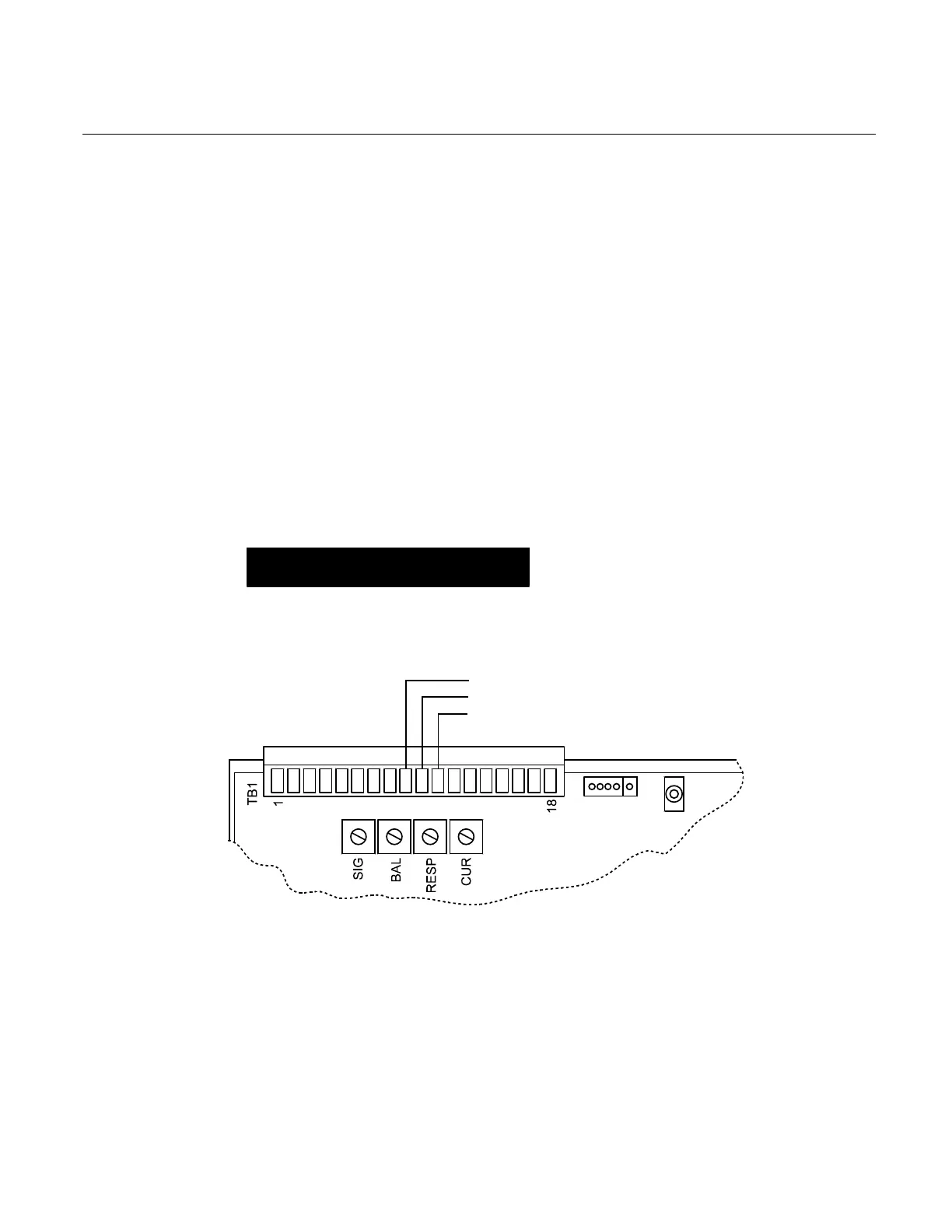
The current limit of the amplifier can be adjusted with the CUR pot from 0 (full CCW) to 100%
(peak full CW). It is a good idea during startup to adjust the CUR pot to its full CCW position
and increase it slowly CW to assure normal operation.
During startup the BAL adjustment can be used to reduce/stop any low speed CW/CCW drift
caused by imbalance between the external command voltage and the amplifier.
Once connected to loads, the crispness of motion (step response) and stability can be
optimized with the RESP pot. Full CW is maximum response.
NOTE
The BAL and RESP pots apply only to
operation in the Velocity Mode; the CUR and
SIG pots apply to both modes.
(10) COMMAND –
(11) GND