8.21.9 Engine Interface Module EIM 2 – Removal and installation
Preconditions
☑ Engine is stopped and starting disabled.
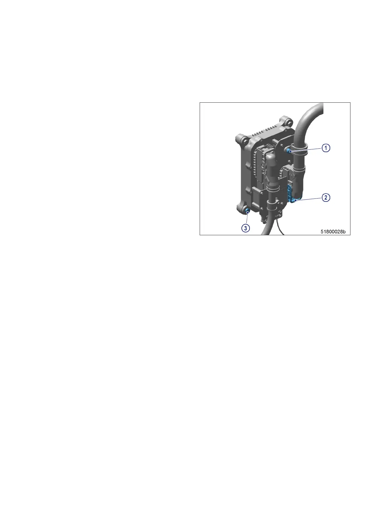
Removing Engine Interface Mod-
ule from engine
1. Note or mark assignment of cables and con-
nectors.
2. Unscrew all screws (1).
3. Undo clips (2) on connectors.
4. Disconnect all connectors.
5. Unscrew power and starter cable.
6. Remove screws (3).
7. EIM 2.
Installing Engine Interface Module on engine
1. Install in reverse order. When doing so, observe correct assignment between cables and connectors.
2. Check seal before installing.
Result: Replace seal if porous or defective.
Downloading software
1. The new EIM 2 still does not have appropriate FSW and parameter/descriptor module (the diagnostic lamp
(DILA) indicates flashing code 4 when the power supply is connected, (→ Page 170)).
2. The FSW and the parameter/descriptor module must first be downloaded from the central database (CDB)
based on the relevant engine number using the DiaSys
®
software tool, and then loaded in the EIM 2.
M015650/06E 2018-05 | Accessories for (Electronic) Engine Governor / Control System | 169
TIM-ID: 0000017035 - 006