6
2. Connections
Connect the ROXXY Smart Control as follows:
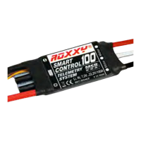
· MSB sensor lead - two-core (a)
This lead should be connected to the MSB socket
on the receiver, which is labelled “S”, “MSB” or
“Sensor”.
· Servo lead - three-core (b)
This lead is connected to the THROTTLE channel on
the receiver (usually channel 4).
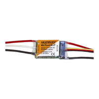
· Motor leads (c)
Connect these leads to the brushless motor.
· Battery leads (d)
Connect these to the ight / drive battery.
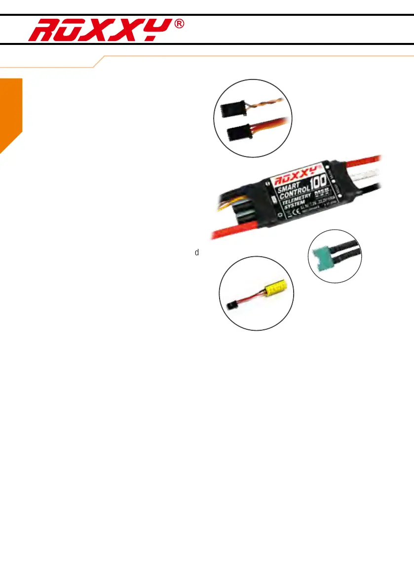
The ROXXY Smart Control 45A and 70A are supplied
tted with MULTIPLEX M6 plugs as standard.
Caution!
MULTIPLEX M6 connectors are designed to handle
continuous currents of up to 35 Ampere. If your mo-
tor draws a continuous current higher than 35A, you
must attach different connectors of higher rating.
Please take great care to maintain correct polarity!
The red wire must be connected to the positive (+)
terminal, the black wire to the negative (-) terminal.
If you intend to use batteries consisting of more than
three cells, we recommend including a MULTIPLEX
Antiash 70 in the circuit. Alternatively use battery
connectors with an integral anti-spark resistor.
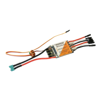
· Smoothing capacitor (e)
The market offers a very large number of servo types
which vary widely in their effect on power supply
voltage. A smoothing capacitor is supplied in the set,
and we recommend tting it in any vacant receiver
socket (e.g. that marked “B/D”). This ensures that
the power supply voltage remains in the optimum
range even when the current load varies greatly, and
when backow currents are present.
Disabling the S-BEC system for use with an ex-
ternal power supply (e.g. external BEC or receiver
battery)
If the speed controller’s BEC specication does not
satisfy your requirements, or if inconsistencies occur
during tests under load (Chapter 4. Preparations),
then we recommend using an external BEC unit or a
separate receiver battery instead of the internal BEC.
Using simultaneously S-BEC and a receiver batte-
ry is not permitted.
This is the procedure for disabling the internal S-BEC
system: use a pointed instrument to raise the plastic
lug which retains the red wire (+) in the housing of the
three-core UNI receiver lead (b), then gently pull the
red wire out of the plastic housing. Insulate the bare
metal parts with a length of heat-shrink sleeve.
(a)
(b)
(d)
(c)
(e)
GB