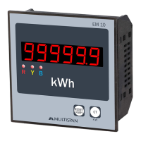
EM 10
RESET
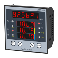
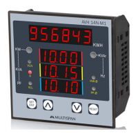
KWH
KW
CT
R
Y
B
kWh
.
www.multispanindia.com
Page-3
EM-10
Allsafetyrelatedcodifications,symbolsandinstructionsthatappearinthisoperatingmanual
orontheequipmentmustbestrictlyfollowedtoensurethesafetyoftheoperatingpersonnelas
wellastheinstrument.
Ifalltheequipmentisnothandledinamannerspecifiedbythemanufacturer,itmightimpairthe
protectionprovidedbytheequipment.
=>Readcompleteinstructionspriortoinstallationandoperationoftheunit.
WARNING:Riskofelectricshock.
3)Cableusedforconnectiontopowersource,musthaveacrosssectionof1mmorgreater.Thesewires
shouldhaveinsulationscapacitymadeofatleast1.5kV.
2)Toreduceelectromagneticinterference,usewirewithadequateratingandtwistsofthesameof
equalsizeshallbemadewithshortestconnection.
1)TopreventtheriskofelectricshockpowersupplytotheequipmentmustbekeptOFFwhiledoingthe
wiringarrangement.Donottouchtheterminalswhilepowerisbeingsupplied.
4)Abetteranti-noiseeffectcanbeexpectedbyusingstandardpowersupplycablefor
theinstrument.
1)Thisequipment,beingbuilt-in-type,normallybecomesapartofmaincontrolpanelandinsuchcase
theterminalsdonotremainaccessibletotheenduserafterinstallationandinternalwiring.
2)Donotallowpiecesofmetal,wireclippings,orfinemetallicfillingsfrominstallationtoenterthe
productorelseitmayleadtoasafetyhazardthatmayinturnendangerlifeorcauseelectricalshockto
theoperator.
3)Circuitbreakerormainsswitchmustbeinstalledbetweenpowersourceandsupplyterminalto
facilitatepowerONorOFFfunction.Howeverthismainsswitchorcircuitbreakermustbe
installedatconvenientplacenormallyaccessibletotheoperator.
4)Useandstoretheinstrumentwithinthespecifiedambienttemperatureandhumidityrangesas
mentionedinthismanual.
WarningGuidelines
InstallationGuidelines
MechanicalInstallation
Maintenance
SafetyPrecautions
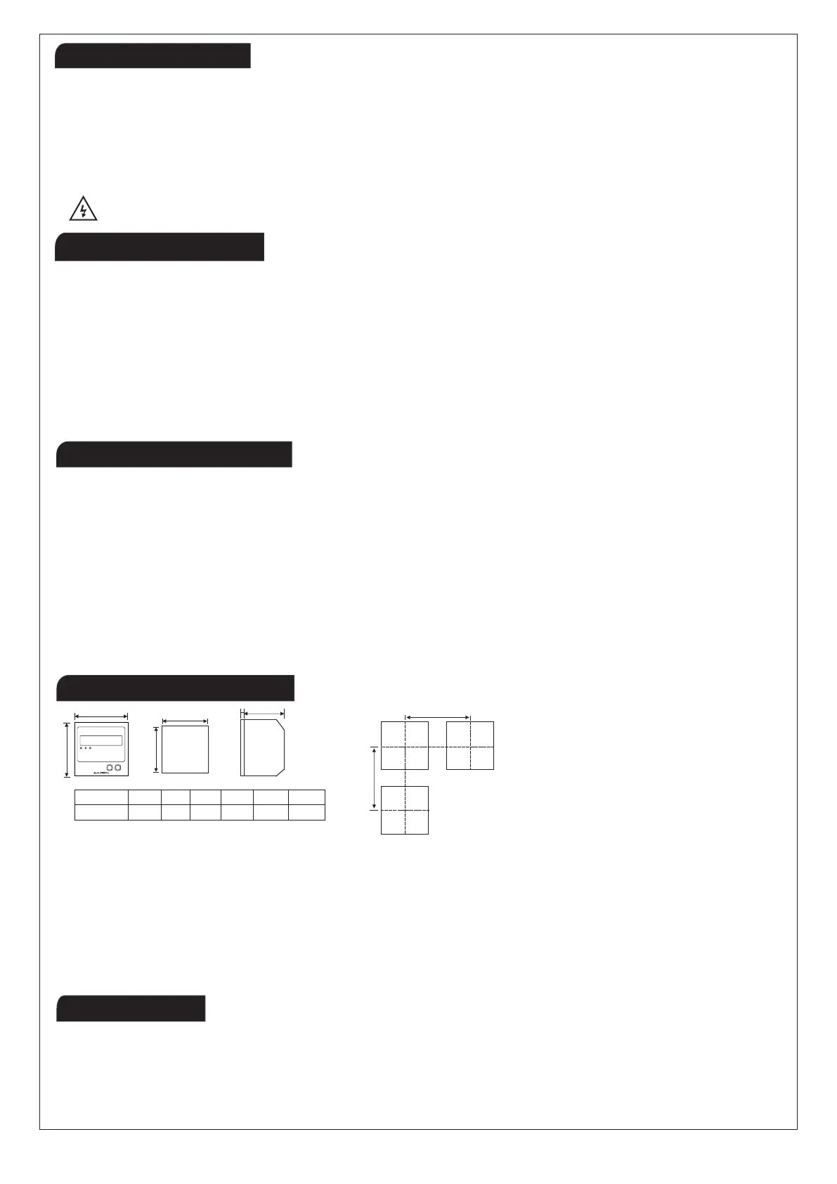
1)Preparethepanelcutoutwithproperdimensionsasshowabove.
2)Fittheunitintothepanelwiththehelpofclampgiven.
3)Theequipmentinitsinstalledstatemustnotcomeincloseproximitytoanyheatingsource,
causticvapors,oilssteam,orotherunwantedprocessbyproducts.
4)Usethespecifiedsizeofcrimpterminal(M3.5screws)towiretheterminalblock.Tighteningthe
screwsontheterminalblockusingthetighteningtorqueoftherangeof1.2N.m.
5)Donotconnectanythingtounusedterminals.
1) The equipment should be cleaned regularly to avoid blockage of ventilating parts.
2)Cleantheequipmentwithacleansoftcloth.Donotuseisopropylalcoholoranyothercleaningagent.
3)Fusibleresistormustnotbereplacedbyoperator.
2
A
B
C
D
E
F
MODEL A
96mm 96mm
92mm
92mm 3mm 50mm
B
C
D E
F
DIMENSIONS
136mm - 5.35 inches
120mm - 4.72 inches