DehumidierML420-MLT1400
4.5.2Ductforoutdoorairinlet
Whenbringingambientairfromoutdoorsintothedehumidier,theinletductopeningmustbelocated
sufcientlyhighabovegroundleveltopreventdustanddebrisfromentering.
Theductingmustbedesignedtopreventrainandsnowfrombeingdrawnintothedehumidier.Theair
inletmustbelocatedawayfrompossiblecontaminantssuchasengineexhaustgases,steamandharmful
vapours.
Topreventthewet(outlet)airfromhumidifyingthereactivation(inlet)air,theairinletforreactivationmust
belocatedatleast2mfromthewetairoutlet.
Attachawirenetwithameshwidthofapproximately10mmintheouterendoftheducttopreventanimals
fromenteringthedehumidierducting.
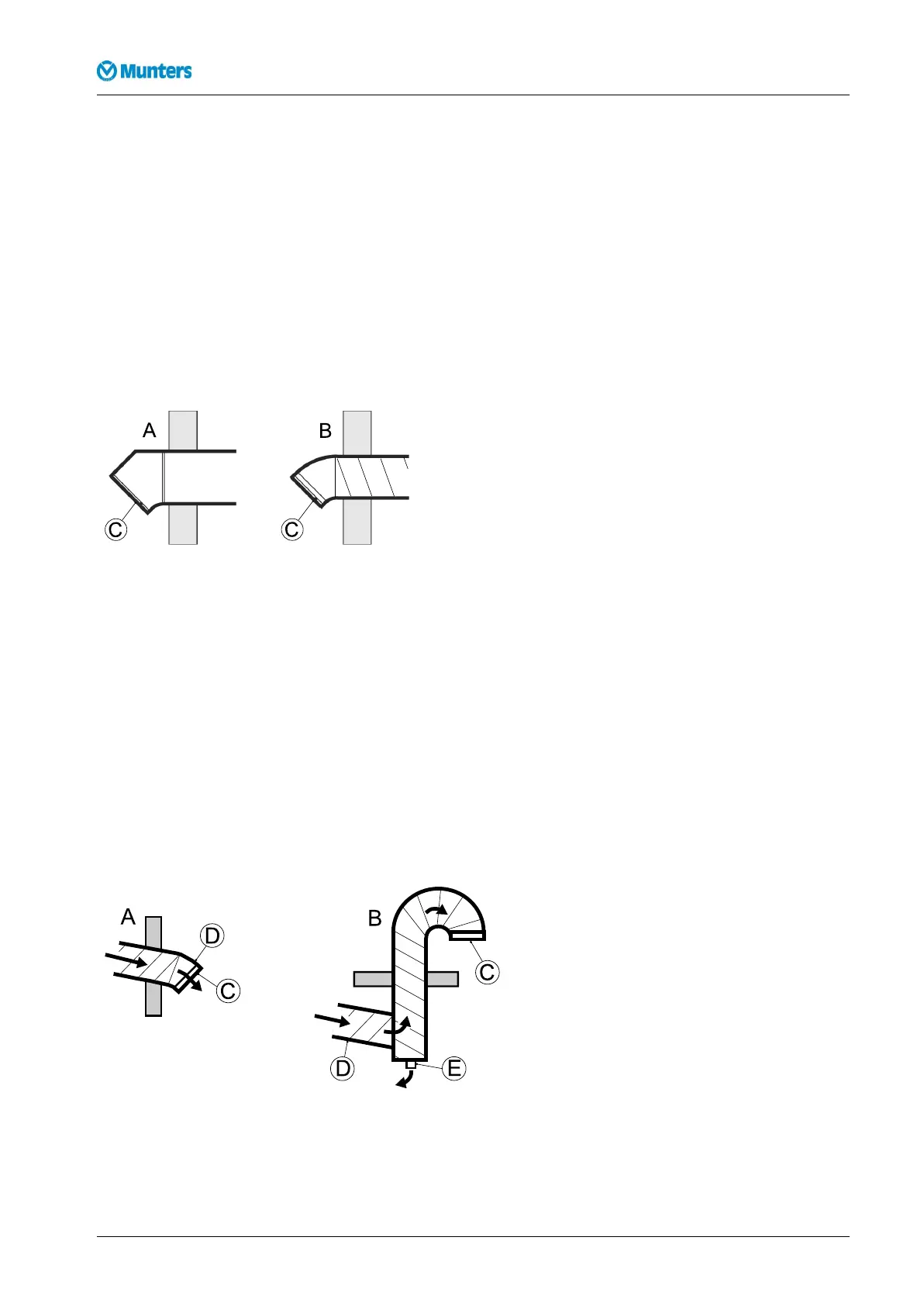
Figure4.6Outdoorairinletdesign
A.Rectangularducting
B.Roundducting
C.Wirenetting
4.5.3Ductforwetairoutlet
Thematerialforthewetairductmustwithstandcorrosionandtemperaturesofupto100°C.Thewetair
ductingmustalwaysbeinsulatedifthereisariskofcondensation.Thewetairleavingthedehumidierwill
easilycausecondensationontheinsideoftheductwallsduetothehighmoisturecontent.
Horizontalductsmustbeinstalledslopingdownwards(awayfromthedehumidier)todrainawaypossible
condensation.Theductslopemustbeatleast2cm/m.Inaddition,drainageholes(5mm)shouldbemadeat
lowpointsintheducttopreventwateraccumulation.
Attachawirenetwithameshwidthofapproximately10mmintheouterendoftheducttopreventanimals
fromenteringthedehumidierducting.
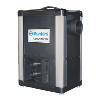
Figure4.7Wetairoutletdesign
A.Horizontalwetairoutlet
B.Verticalwetairoutlet
C.Wirenetting
D.Downwardslope
E.Condensatedrainage
12Installation190TGB-1035-H1604