2.5.4 EnergyRecoveryPurgeandEnergyEfficiencyPurge
1
2
3
4
7
6
5
6
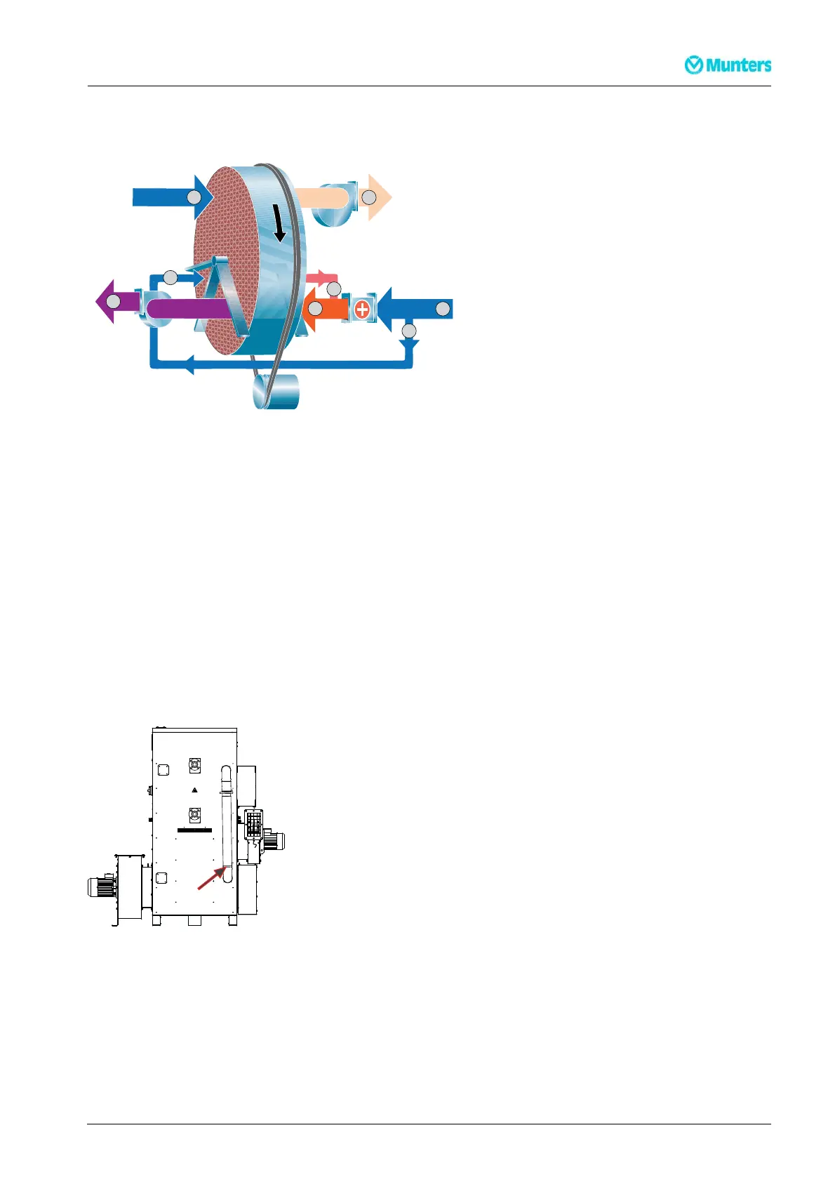
Figure 2.9 Principle for Energy Recovery Purge and Energy Efficien cy Purge
1. Reactivation air
2. Heated reactivation air
3. Wet air
4. Pr ocess air
5. Dry air
6. Purge air
7. Warm purge air
Energy Recover y Purge (ERP) and Energ y Efficiency Purge (EEP) are two energy saving solutions that
recycles heat f rom the rotor, after the reactivation section in the rotational direction of the rotor. A minor
part of the reactivation airflow is bypassed to the war m sector of the rotor, before the airflow enters the
reactivation heater. T he airflow is heated up by the rotor and then mixed with the reactivation airflow, after
the r eactivation heater. The recycled heat from the rotor increases the efficiency and reduces the energy
consumption.
Compared to a standard unit, ERP will give the same dehumidification capacity with reduced reactivation
heater energ y. With EEP, the reactivat ion heater energy is the same as in a standard unit, while the
dehumidification capacity is increased.
Thepurge airflow duct on MX² 30 is installed on the rear side of the unit. The purge airflow (ERP, EEP,
LDP)canbeadjustedwithadamperinstalledontheduct.
MX² 30
Figure 2.10 Purge airflow duct
Thepurge airflow duct on MX² 35–95 is located inside the unit and the purge airflow (ERP, EEP) cannot be
adjusted. An a djustable damper for Low Dewpoint Purge is located on top of the unit.
190TEN–108 9–G1412
Dehumidifierdesign
15