V 1.6 23
4. Diagnostics
4.1 LED Display
Channel-related diagnostics are displayed by the LED assigned to the channel on the M12
socket. On the right next to the BUS LED, there are four LEDs that display the power supply
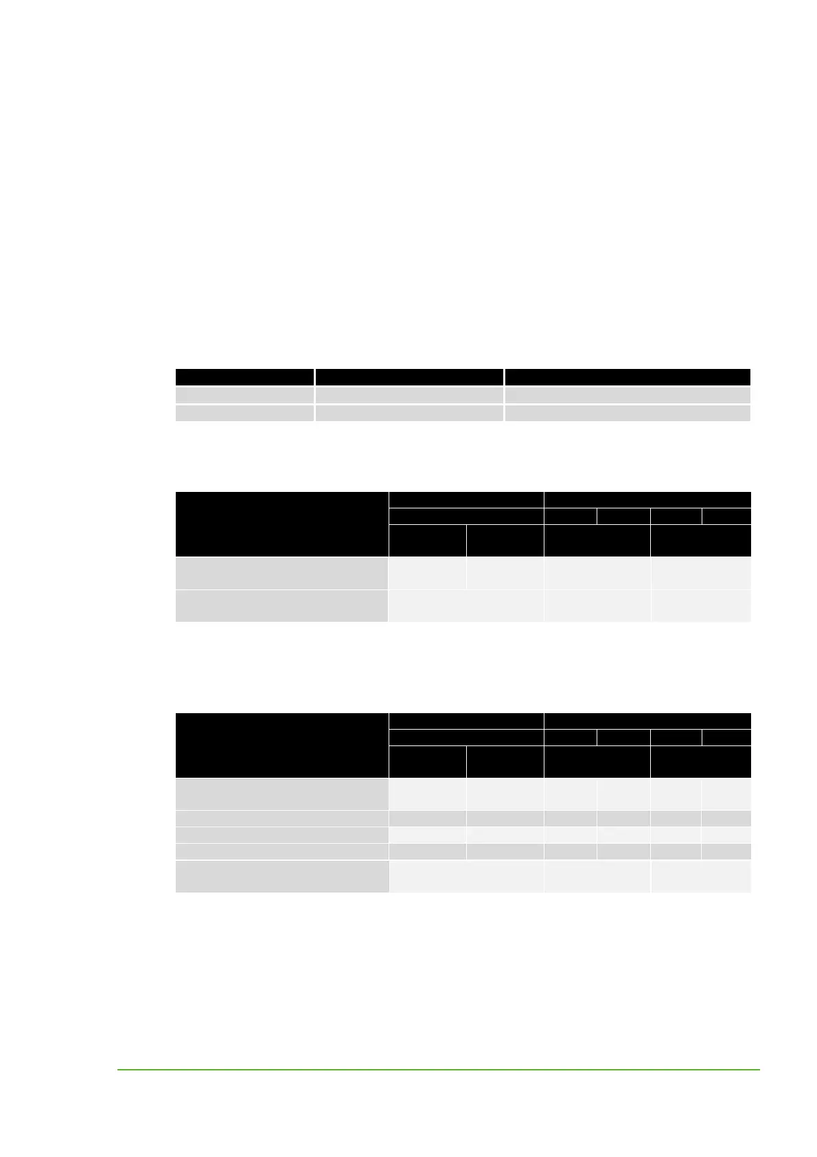
status. The tables below indicated the relationship between the fault cause and the LED display.
BUS LED
LED Display Description
Bus Run
Green fixed light Bus runs OK
Bus Run
OFF Bus not initalized, bus not OK
Table 5: BUS-LED
IMPACT67-P DI16, Art.No. 55345
Error
LED at M12 socket LED Designation
Socket no. x U
S
U
S
Channel
0x
Channel
1x
Erro
POWER
Table 6: LED Display of the IMPACT67-P DI16
IMPACT67-P DI8 DO8, Art.No. 55346
Error
LED at M12 socket LED Designation
Socket no. x U
U
S
U
U
S
Channel
0x
Channel
1x
Erro
POWER
Module power supply
undervoltage
Red OFF OFF
I/O power supply undervoltage Red OFF OFF
No actuator supply OFF OFF
Actuator shutdown Red Red
Table 7: LED Display of the IMPACT67-P DI8 DO8
Module power supply
undervoltage
Red
>18 V
green
Short-circuit (sensor power
supply)
both red
Short-circuit (sensor power
supply)
both red
www.comoso.com

 Loading...


