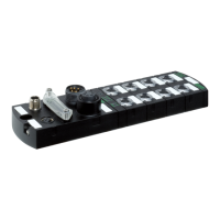
IMPACT67-P manual
14 V 1.6
2.3 Wiring-Up
2.3.1 Wiring Up the Profibus
Cables
The bus line must be designed to EN 50170 Part 2 (line type A). To ensure the simplest and
most reliable wiring possible, we recommend using our Prewired Profibus lines.
Please refer to our accessory information on page 36.
Connecting to IMPACT67-P
Connect function ground with FE connection to casing.
Connect incoming Profibus cables to incoming bus terminal.
Connect any continuing Profibus cables to continuing bus terminal
or screw on terminating resistor to continuing bus terminal.
Each Profibus segment must be installed with a terminating resistor at start
and end.
2.3.2 Connecting the Power Supply
The module may be damage if the power supply unit has the incorrect
polarity. We therefore recommend you use our prewired 7/8 lines.
Connecting the Power Supply to the Module
Auxiliary power is required to feed the actuators and sensors. The IMPACT67-P electronics are
powered by the sensor power supply.
The sensor power supply should not be switchable.
The 7/8“ connector is designed for a maximum current of 9 A per pin. This
must be considered if the power supply has additional loops.
www.comoso.com

 Loading...