2205B0JE-DA-J-N_2014.05.
5 Maintenance and Inspection
Screw Compressor J-series 5.4 Disassembly and Assembly of the Compressor
5-22
12. Remove the bottom four hexagon socket head cap screws (M16×60 for 170J, M16×75 for 220J,
M20×110 for 280J), which connect the main rotor casing with the bearing head, and the suction
cover.
Make sure that the lifting equipment and wires have sufficient load capacity for
the compressor. Otherwise, the compressor may fall, resulting in death or
injuries and damage to the compressor. Do not allow anyone to be under the
lifted compressor. (Compressor weight: 700 kg for 170JS, 730 kg for 170JM, 775
kgor 170JL, 1270 kg for 220JS, 1330 kg for 220JM, 1400 kg for 220JL, 2300 kg for
280JS, 2450 kg for 280JM, 2600 kg for 280JL)
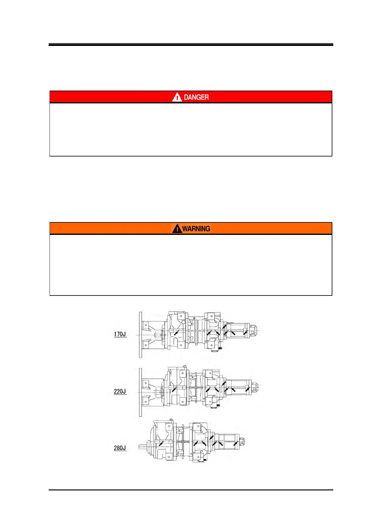
5.4.5 Removing Oil from Inside the Compressor
While placing the compressor on the work bench, remove the drain plug at the bottom of the
compressor as shown in the figure 5-2 and drain lubricant.
Make sure to reattach the removed plugs to the original positions (to prevent any plug being lef
detached).
If there is residual high-pressure gas/refrigerant or high-pressure oil dissolved in
refrigerant within the hydraulic cylinder (variable Vi cylinder and capacity control
cylinder), the refrigerant gas or oil may blow off when the oil drain plugs are
removed. This may result in injury such as frostbite and loss of vision. Therefore
always check and confirm the pressure in the hydraulic cylinder, before the oil
drain plugs are opened, and wear protective equipments such as goggles and
chemical resistant gloves.
Figure 5-2 Positions of Drain Plugs