EasyManuals Logo

mycom 3225**C Series User Manual

mycom 3225**C Series
172 pages
To Next Page IconTo Next Page
To Previous Page IconTo Previous Page
Page #165 background imageLoading...
Page #165 background image
2202MYJE-MY-C8-N_2018.02.
Chapter 7 Related Documents
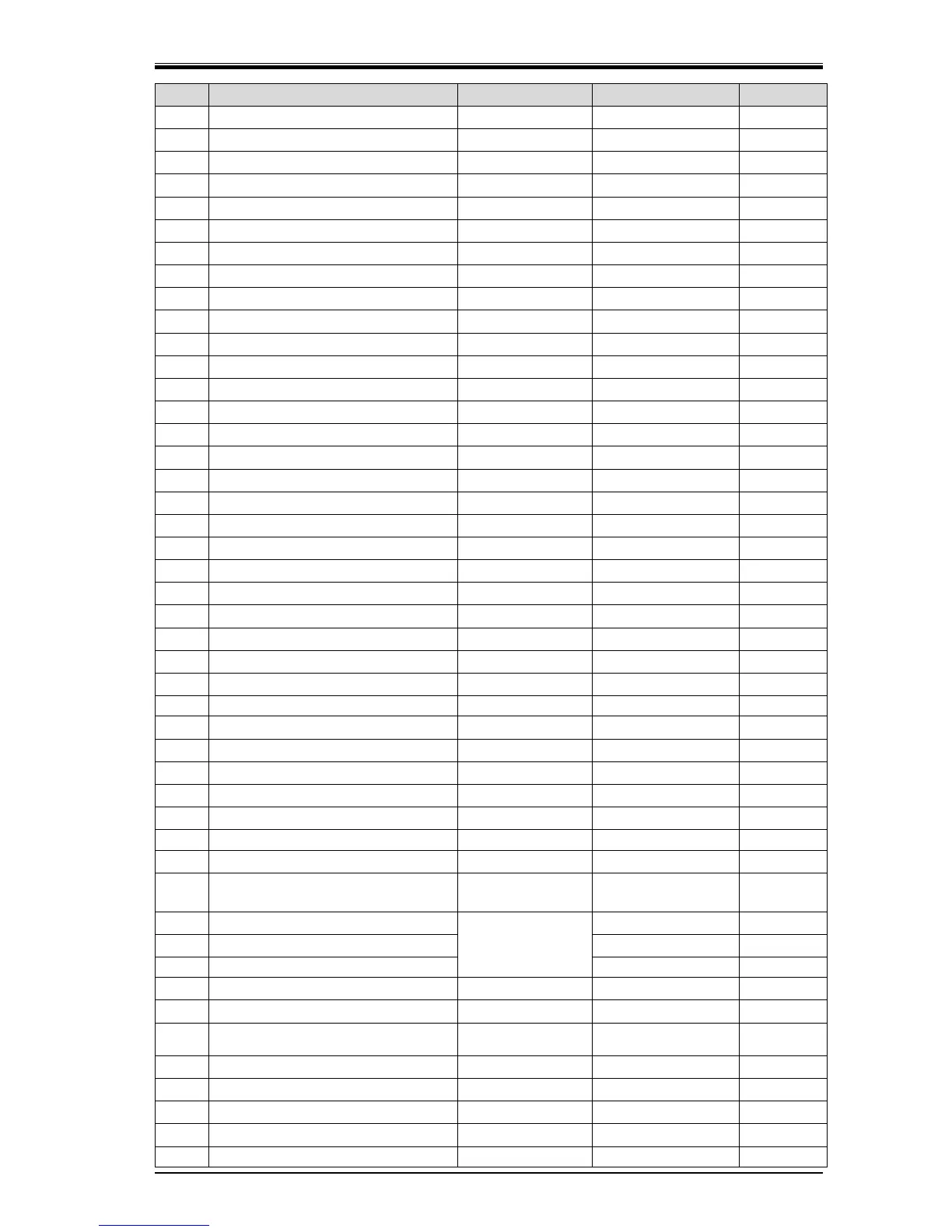
Compound 2-stage Screw Compressor 3225**C Parts Configuration Table
7-31
P/N
Part Name
Code No.
Remarks
Qty.
92-1
Suction Flange (1) with hole
CS71300-350
JIS 20K 350A (14")
1
92-1
Suction Flange (1) without hole
CS71300-P350
JIS 20K 350A (14")
1
92-2
Suction Flange (2) with hole
CS71300-200
JIS 20K 200A (8")
1
92-2
Suction Flange (2) without hole
CS71300-P200
JIS 20K 200A (8")
1
93-1
Gasket, Suction Flange (1)
CS71200-350N
JIS 20K 350A (14")
1
93-2
Gasket, Suction Flange (2)
CS71200-200N
JIS 20K 200A (8")
1
94-1
Hexagon Head Bolt
NB12030-080P3
M30P3×80
16
94-2
Hexagon Head Bolt
NB12022-055
M22×55
12
95-1
Discharge Flange (1) with hole
CS71300-200
JIS 20K 200A (8")
1
95-1
Discharge Flange (1) without hole
CS71300-P200
JIS 20K 200A (8")
1
95-2
Discharge Flange (2) with hole
CS71300-150
JIS 20K 150A (6")
1
95-2
Discharge Flange (2) without hole
CS71300-P150
JIS 20K 150A (6")
1
96-1
Gasket, Discharge Flange (1)
CS71200-200N
JIS 20K 200A
1
96-2
Gasket, Discharge Flange (2)
CS71200-150N
JIS 20K 150A
1
97-1
Hexagon Head Bolt
NB12022-055
M22×55
12
97-2
Hexagon Head Bolt
NB12022-055
M22×55
12
100
Mechanical Seal Assembly
CS10000-320BE
BOS-E1
1
100
Mechanical Seal Assembly
CS10002-320EBS
BBS-E
1
100
Mechanical Seal Assembly
CS10001-320BBS
BBS3
1
120-1
Unloader Indicator Assembly (1)
CS12000-1612F
1612**C
1
120-2
Unloader Indicator Assembly (2)
CS12000-3225
3225C (2) 30-100%
1
125-1
Micro Switch Set (1)
CS1259-C
125L**
1
125-2
Micro Switch (2)
CS12500-200
200*** Z15GW
2
127-1
Micro Switch Cam (1)
CS12700-125F
125L** 0-100%
1
127-2
Micro Switch Cam (2)
CS12700-322530
3225*SC/*MC (2)
1
127-2
Micro Switch Cam (2)
CS12700-200F
3225*LC (2)
1
129-1
Potentiometer (1)
CS1299-J
1612 1k with lead wire
1
129-2
Potentiometer (2) 200-1k
CS1299-E10
with lead wire
1
137-1
Indicator Dial (1)
CS13700-1612CA
1612**C
1
137-2
Indicator Dial (2)
CS13700-3225C
3225*SC/*MC (2)
1
137-2
Indicator Dial (2)
CS13700-200
3225*LC (2)
1
202-1
Bevel Gear
CS20100-1612C6
1612 ID 6mm
2
150
O-ring
PA12-220
JIS B 2401 G220
2
-
Gear Coupling Assembly (Current Type)
CS1519-M
151+152+153+159
1
-
Gear Coupling Assembly (Old Type)
CS1519-M
151+152+153+159
+154+155
-
151
Drive Sleeve
CS15100-3225C
3225**C IUS-A-30
1
152
Drive Hub
3225**C IUS-A-30
2
154
Stopper, Drive Sleeve
3225**C IUS-A-30
2
155
Stop Ring
-
FRS-130
4
157
Key, Driven Hub & Drive Hub
CS15700-3225CH
20×12×84
2
159
Set Screw
NA83610-025
M10×16 knurled,
with anti-loosening
1
160
Lock Nut
NG31-015
AN15
1
161
Lock Washer
NG32-015
AW15
1
162
Hexagon Socket Head Cap Screw
NB35412-050
M12×50
5
164
Retainer, Oil Injection Pipe
CS16400-3225C
3225**C
1
165
O-ring
PA11-040
JIS B 2401 P40
1

Table of Contents

Questions and Answers:

Question and Answer IconNeed help?

Do you have a question about the mycom 3225**C Series and is the answer not in the manual?

mycom 3225**C Series Specifications

General IconGeneral
Brandmycom
Model3225**C Series
CategoryCompressor
LanguageEnglish

Related product manuals