2205B0JE-DA-J-N_2014.05.
5 Maintenance and Inspection
Screw Compressor J-series 5.4 Disassembly and Assembly of the Compressor
5-42
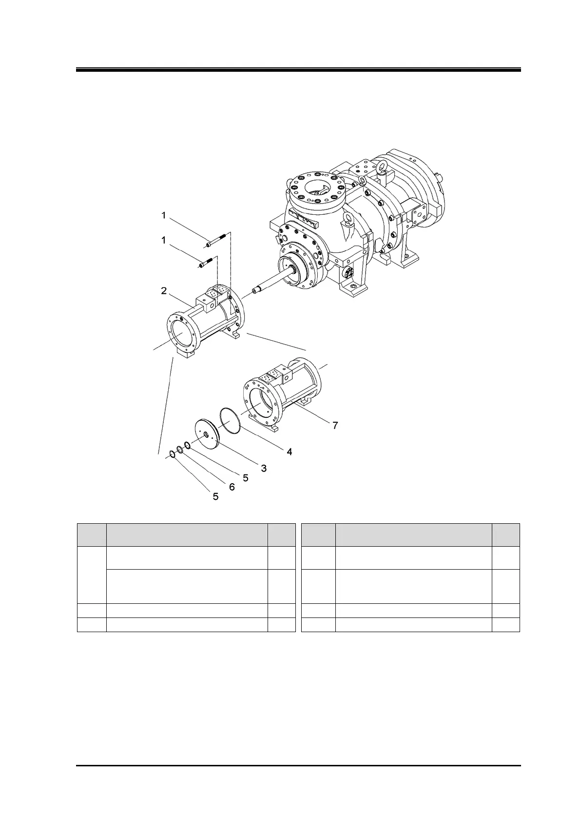
5.4.12 Unloader Cylinder
170J/220J/280J
Order Description
Part
No.
Order Description
Part
No.
1
Hexagon socket head cap screw
(M12×70/M16×90/M20×110)
61 4 O-ring (G135/G175/G230) 298
Hexagon socket head cap screw
(M12×110/ M16×140/ M20×170)
62 5
Back-up ring for O-ring
(SUN-2BP 32/ SUN-2BP 44/
SUN-2BP 58)
325-2
2 Unloader cylinder assembly — 6 O-ring (P32/P44/P58) 325-1
3 Partition plate, unloader cylinder 297 7 Unloader cylinder 60
1. Remove the parts in the order of the numbers shown in the figure.
2. Install the parts in the reverse order of removing.