2205B0JE-DA-J-N_2014.05.
5 Maintenance and Inspection
Screw Compressor J-series 5.4 Disassembly and Assembly of the Compressor
5-60
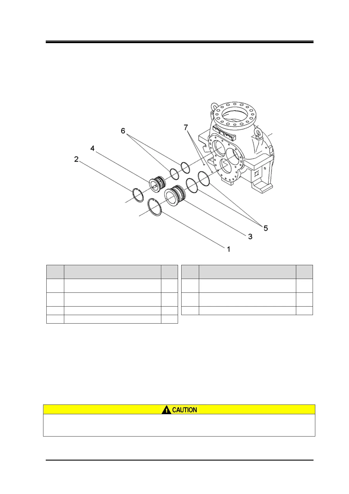
5.4.18 Suction Cover
170J/220J/280J
Order Description
Part
No.
Order Description
Part
No.
1
Retaining ring C type internal
(H120/H150/H190)
29-1 5 O-ring (G100/G130/G165) 432
2
Retaining ring C type internal
(H95/H120/H150)
29-2 6 O-ring (G75/G100/G100) 433
3 Bearing, male rotor 27 7 Spring pin (4 dia.×10) 14
4 Bearing, female rotor 28
1. Remove the parts in the order of the numbers shown in the figure.
2. Install the parts in the reverse order of removing.
5.4.18.1 Common Precautions for Removal/Installation
Retaining ring
The retaining ring may jump out, causing injuries. Always use retaining ring pliers
of appropriate size and wear protective goggles.
 Loading...


