2205B0JE-DA-J-N_2014.05.
2 Structure and Specifications of the Compressor
Screw Compressor J-series 2.5 Mechanisms
2-25
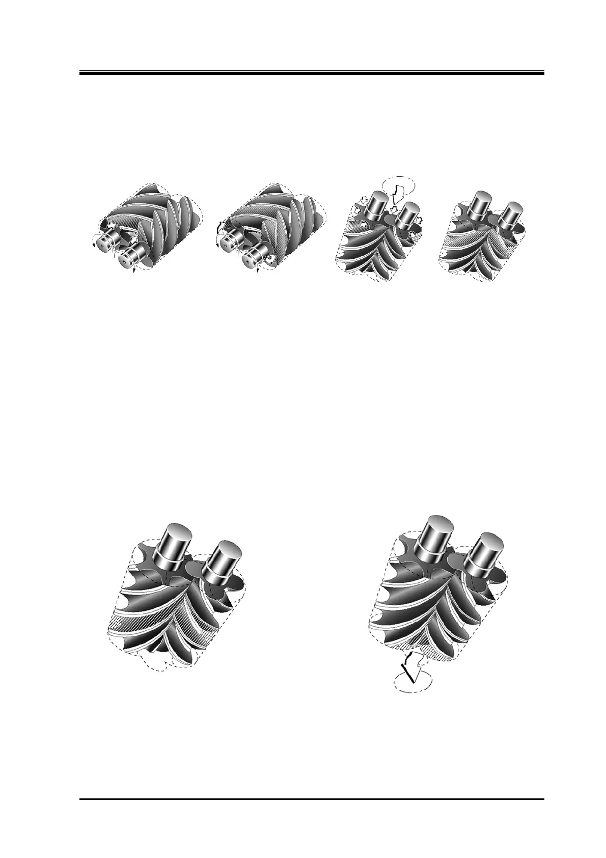
2.5.2 Suction Process
As show in Figure 2-18, rotors with different lobe profiles that mesh intricately start the suction process.
The volume enclosed between the M and F rotor lobes and compressor casing increases from the
suction side as the rotors turn. When the volume is at its maximum, the rotors start to trap the gas
between the lobes and compressor casing thereby isolating the gas from the suction port.
(1) Start of suction (2) Suction continues (3) Just before suction
completion
(4) Suction side sealed
Figure 2-18 Suction Process
2.5.3 Compression Process
As the rotors further rotate, the sealing line between them moves toward the discharge side and the
volume between the rotor lobes decreases and compresses the trapped gas. (Refer to Figure 2-19)
2.5.4 Discharge Process
The volume between rotor lobes decrease to a predetermined value at the discharge port. As the rotors
further rotate, the compressed gas is pushed out from the discharge port to the outlet of the compressor.
(Refer to Figure 2-20)
Figure 2-19 Compression Process Figure 2-20 Discharge Process