2205B0JE-DA-J-N_2014.05.
5 Maintenance and Inspection
Screw Compressor J-series 5.4 Disassembly and Assembly of the Compressor
5-25
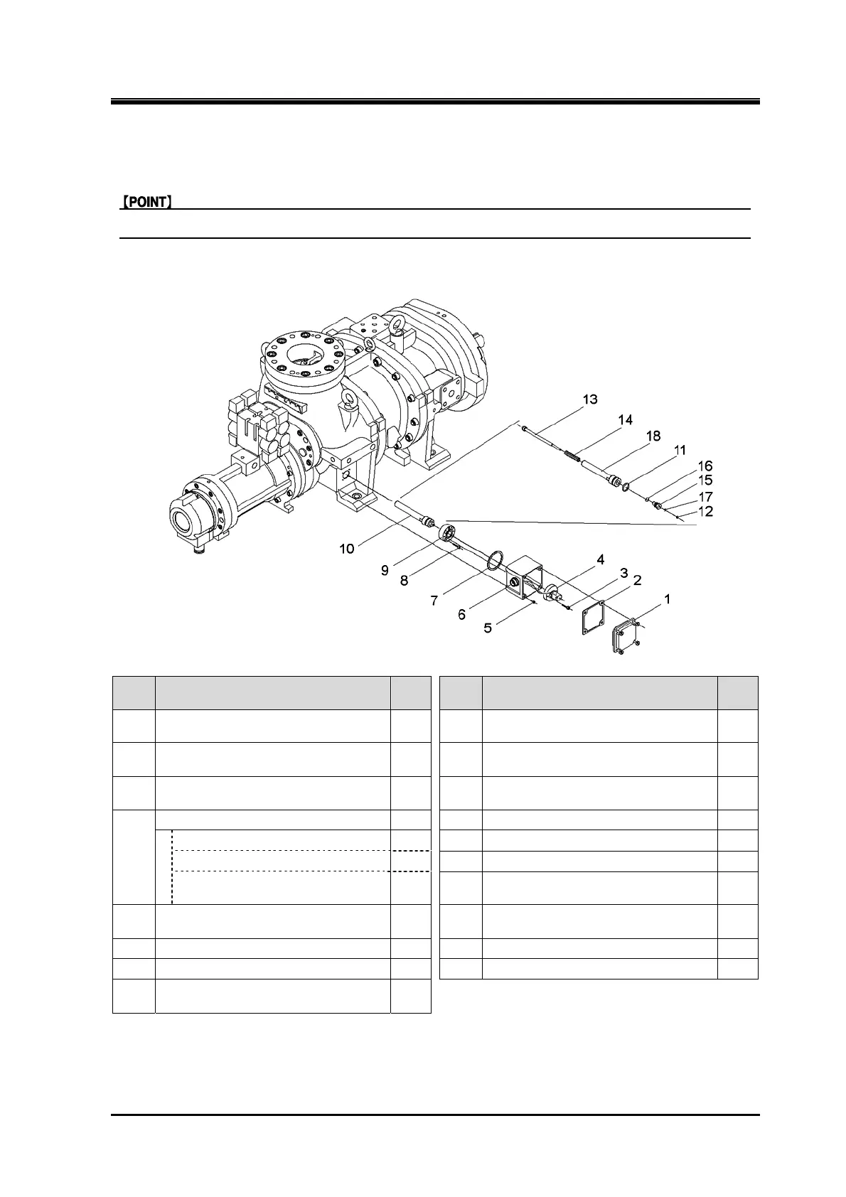
5.4.7 Vi Position Sensor
Assemble the Vi position sensor finally after assembling all other parts.
170J/220J/280J
Order Description
Part
No.
Order Description
Part
No.
1 Sensor box lid — 9
Gland, Vi position sensor rod
housing
718
2 Sensor box lid packing — 10
Vi position sensor rod housing
assembly
—
3
Hexagon socket head cap screw
(M6×25)
723 11 O-ring (G25) 717
4
Potentiometer assembly — 12 Retaining ring E type 716
Potentiometer — 13 Vi position sensor rod 712
Vi position sensor support — 14 Spring 711
Hexagon socket head cap
screw (M3×10)
— 15 Plug, Vi position sensor rod 715
5
Hexagon socket head cap screw
(M5×15)
726 16 O-ring (P12) 713
6
Sensor box 724 17 O-ring (P6)
714
7
Packing, Vi position sensor box 725 18 Vi position sensor rod housing
709
8
Hexagon socket head cap screw
(M6×25)
719
1. Remove the parts in the order of the numbers shown in the figure.
2. Install the parts in the reverse order of removing.
Note: For the details about the Vi position sensor, separately, refer to the special instruction manual.