EasyManuals Logo
Home>mycom>Air Compressor>J Series

mycom J Series User Manual

Default Icon
209 pages
To Next Page IconTo Next Page
To Previous Page IconTo Previous Page
Page #146 background imageLoading...
Page #146 background image
2205B0JE-DA-J-N_2014.05.
5 Maintenance and Inspection
Screw Compressor J-series 5.4 Disassembly and Assembly of the Compressor
5-72
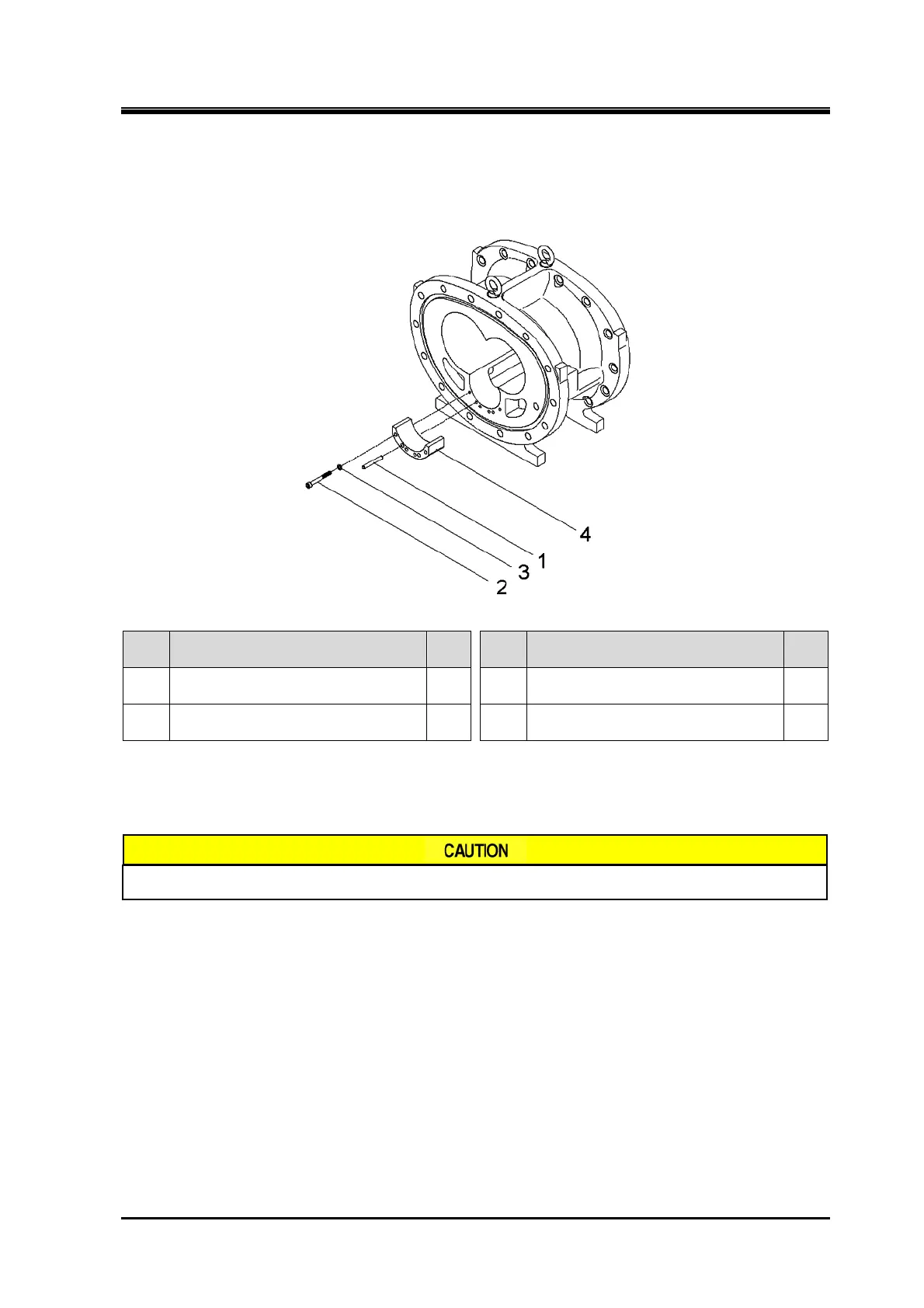
5.4.23 Unloader Slide Valve Guide
Order Description
Part
No.
Order Description
Part
No.
1
Parallel pin
(8 dia.×60/8 dia.×80/13 dia.×100)
249 3 Spring lock washer 248
2
Hexagon socket head cap screw
(M8×70/M8×90/M10×110)
247 4 Guide, unloader slide valve 246
1. Remove the parts in the order of the numbers shown in the figure.
2. Install the parts in the reverse order of removing.
For periodic inspection, do not remove the unloader slide valve guide.

Table of Contents

Other manuals for mycom J Series

Questions and Answers:

Question and Answer IconNeed help?

Do you have a question about the mycom J Series and is the answer not in the manual?

mycom J Series Specifications

General IconGeneral
Brandmycom
ModelJ Series
CategoryAir Compressor
LanguageEnglish

Related product manuals