2205B0JE-DA-J-N_2014.05.
7 Related Documents
Screw Compressor J-series 7.2 List of Tightening Torques for Bolts and Nuts
7-26
Lock Nut/FU Nut (170J/220J/280J)
Part
No.
Tightening point
Tightening torque
N・m (kgf・cm)
Qty. Remarks
170J
39-1 Thrust bearing assembly, male rotor 410(4100) 1 Locknut AN12
39-2 Thrust bearing assembly, female rotor 200(2000) 1 Locknut AN09
69 Unloader piston 80(800) 1 FU nut FU05SS
486 Valve disc 50(500) 1 FU nut FU04SS
220J
39-1 Thrust bearing assembly, male rotor 980(9800) 1 Locknut AN16
39-2 Thrust bearing assembly, female rotor 410(4100) 1 Locknut AN12
69 Unloader piston 80(800) 1 Locknut AN07
486 Valve disc 80(800) 1 FU nut FU05SS
280J
39-1 Thrust bearing assembly, male rotor 1900(19000) 1 Locknut AN20
39-2 Thrust bearing assembly, female rotor 980(9800) 1 Locknut AN16
69 Unloader piston 170(1700) 1 Locknut AN09
Note 1: On June 14, 2010, the "Lock Nut Tightening Angle Range Control Standard" has been
introduced to our compressor manufacturing division, to control the specified tightening
torque for rotor shaft lock nuts (【39-1】【39-2】 in tables above) as follows. Accordingly, the
tightening angle range is now added to the rotor shaft lock nut tightening procedure in this
manual.
Tightening Angle Range of Lock Nuts for Rotors
a) After tightening the lock nut by hand, further tighten the lock nut by using a lock nut wrench until the
rotor starts to turn. Take care not to over-tighten.
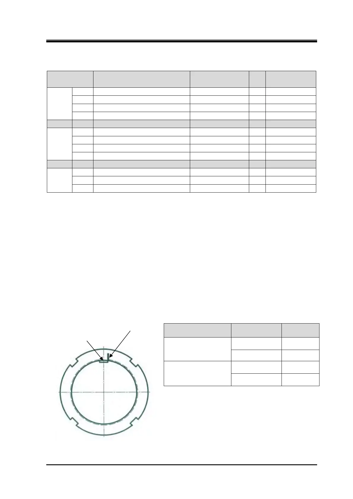
b) Put a mark on the lock nut at the right side edge of the rotor groove where the stopper tongue of the
lock washer fits in, as shown in Figure 7-9.
c) From this marking position, tighten the lock nut in such a way that rotation can be stopped within the
tightening angle range shown in Table 7-3. When measuring the angle, use an angle gauge which is
set to the diameter of rotor shaft.
Table 7-5 Tightening Angles Specified
for Lock Nuts of Rotor
* When tightening lock nut, tightening start position
differs between the first time tightening and the
tightening for the second time or after. Therefore,
angle ranges are specified also for the second
time tightening.
Figure 7-9 Position where mark is put
Model
Angle
range
First time tightening
170J & 220J
& F rotor of 280J
30°to 40°
M rotor of 280J 25°to 35°
Second time tightening
170J & 220J
& F rotor of 280J
20°to 30°
M rotor of 280J 15°to 25°
Marking
Rotor groove (slot)
where stopper tongue of
the lock washer fits
 Loading...


