2205B0JE-DA-J-N_2014.05.
2 Structure and Specifications of the Compressor
Screw Compressor J-series 2.3 Compressor Specifications
2-4
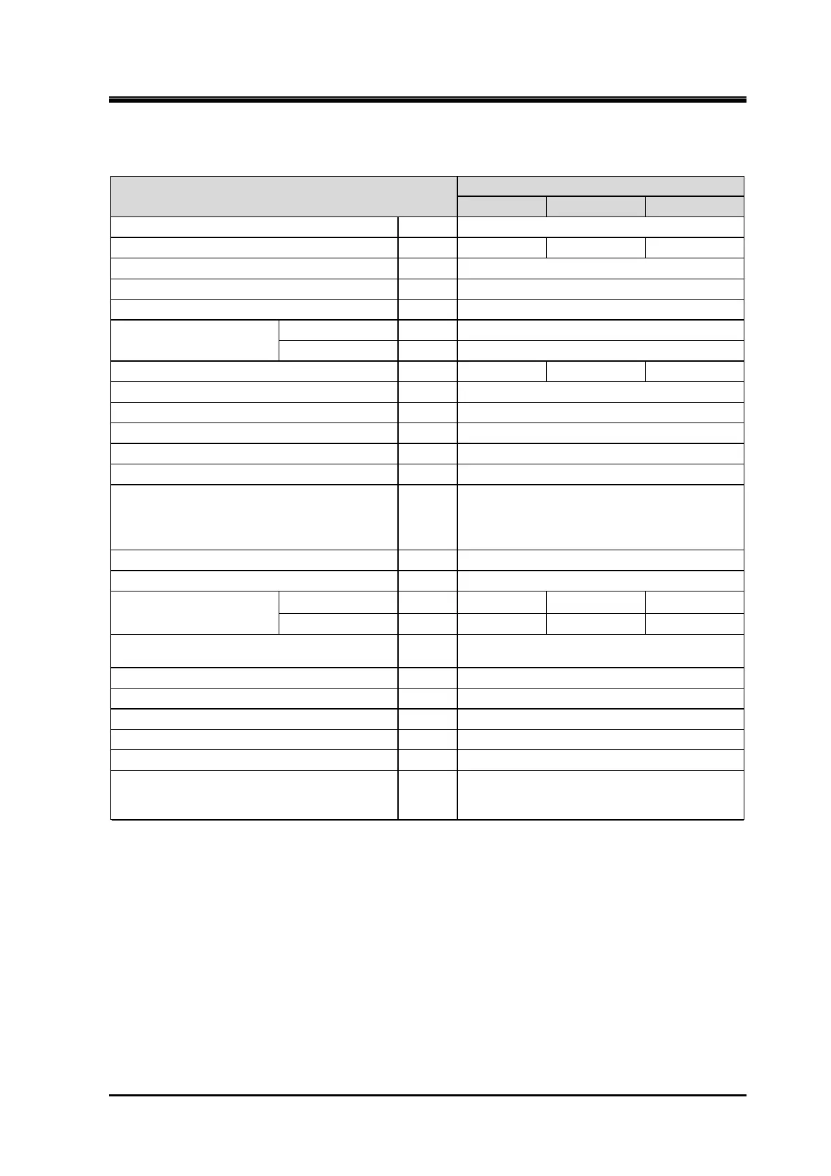
Table 2-3 Specifications of the 280J-Series Compressor
Item
280
S M L
Refrigerant – NH
3
, HFC, CO
2
, Propane, and Propylene
Weight kg 2285 2435 2585
Rotation direction – CCW viewed from motor
Minimum rotation min
-1
1450
Maximum rotation min
-1
3600
Allowable maximum @3550 min
-1
kW 1650
input power @2950 min
-1
kW 1375
GD2 kgm
2
4.887 6.134 7.765
Suction flange – ANSI #300 12”
Discharge flange – ANSI #300 8”
Oil supply (discharge side) – ANSI #300 1”
Oil supply (suction side) – ANSI #300 3/4”
Oil injection oil supply – ANSI #300 1 1/4”
Capacity control and Vi control oil
supply/drain
–
Capacity control Increase/Decrease
: Rc1/2 on each side
Vi control Increase/Decrease
: Rc1/2 on each side
E port – ANSI #300 2 1/2”
I port – ANSI #300 1”
Theoretical
displacement
@3550 min
-1
m
3
/h 2269 2949 3839
@2950 min
-1
m
3
/h 1886 2451 3190
Capacity control (actual load)
–
25 to 100%
(or 30 to 100% in the case of L size)
Vi control – Standard: 2.5 to 5.0
Design pressure MPa 3.5
Suction check valve (integrated) – N/A
Solenoid valve (integrated) – N/A
Flange motor – Non-Available
Oil filter
–
β
20
≥ 150
(For more information, refer to Section
3.2.5.3 in this manual Chapter 3)
Note 1: In this manual unless otherwise noted, pressure units MPa represents the gauge pressure.
Note 2: The connection flanges of the compressor conform to ANSI CLASS 300.
 Loading...


