REFRIGERATION DIVISION
V SERIES
SCREW COMPRESSOR HANDLING MANUAL
Supersedes all previous version. This information is for reference use only and subject to change without notice
Revision 2 (June 05,2000) Page 28 of 61
b) Loosen the lock nut (69) using the lock nut wrench provided in the tool kit.
If the wrench does not reach the nut, turn the Vi changing rod counterclockwise to shift the
variable Vi slide valve (289) to the L port position and then pull the piston out further.
c) Pull out the unloader piston using two eyebolt screws secured in the two screw holes located
in the unloader piston.
d) The unloader cylinder is fitted to the blind cover (22) by two short hex-head socket cap screws
(61) and to the suction cover by six long hex-head socket cap screws (62).
Remove the bolts and pull out the cylinder.
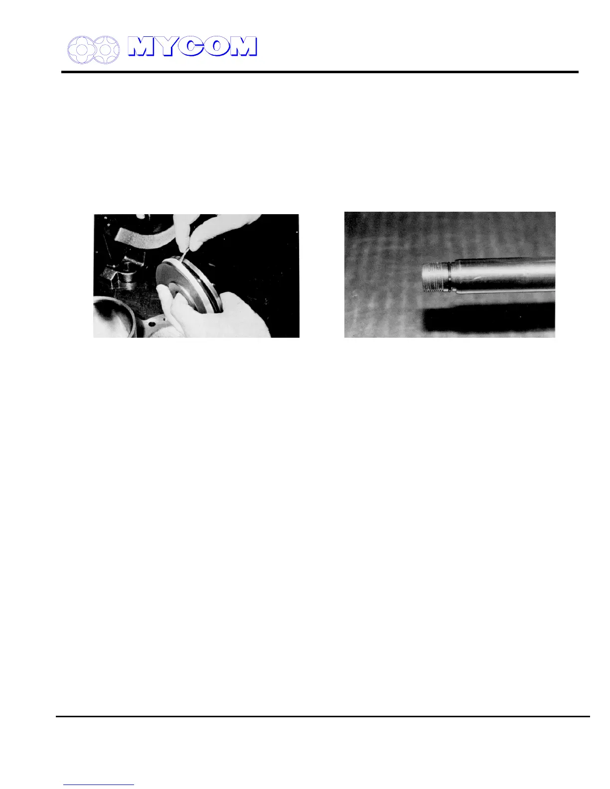
Fig. 38 Checking Unloader Piston Cap Seal (66) Fig. 39 Push Rod (67) and O-Ring
And O-Ring (65)
e) Alternately, the blind cover and cylinder can be removed together as an assembly from the
suction cover by removing the six long hex-head socket cap screws (62) securing the cylinder
to the suction cover and the blind cover fitting screws (24). In this case, the cylinder will not
drop off even if the bolts are removed because the cylinder remains fixed to the suction cover.
Draw out the cylinder from the suction cover and disassemble.
3.4.4.2 Inspection
a) Inspect the cap seal (66) and O-ring (65) on the unloader piston (64) and replace if any
damage or abnormality is found.
These parts should be replaced at least once every two years.
b) The inner surface of the cylinder may sometimes be coated with oil residue or scored.
Finish the inner surface with fine emery paper after cleaning.
c) Inspect the push rod (67) and O-ring (65) on the unloader piston and the O-ring (63) on the
cylinder. If the O-rings show signs of deformation, or have become hardened, replace with
new ones.
3.4.5 Blind Cover (22)
Remove the bolts (24) that secure the blind cover (22) to the suction cover (5), leaving one bolt in
place at the top to prevent the cover from falling suddenly.
The blind cover is fitted to a flat flange (92) on the suction cover and is held in place with the bolts
only. When the gasket has come free, support the cover firmly and remove the last bolt. If the gasket
adheres to the cover and flange, tap the side of the blind cover lightly with a hammer to separate the
gasket.