REFRIGERATION DIVISION
V SERIES
SCREW COMPRESSOR HANDLING MANUAL
Supersedes all previous version. This information is for reference use only and subject to change without notice
Revision 2 (June 05,2000) Page 31 of 61
the peripheral clearance and elasticity of the O-ring but sleeve wear is not unusual. Inspect the O-ring
(35) and replace if any deformation is found.
3.4.7 Bearing Cover (16)
The structure of this portion of the compressor differs between Model D and Model G units.
Model D is provided with a discharge flange (95). For this reason the weight of Model D units is
unbalanced, so particular care should be taken when working with it.
3.4.7.1 Disassembly
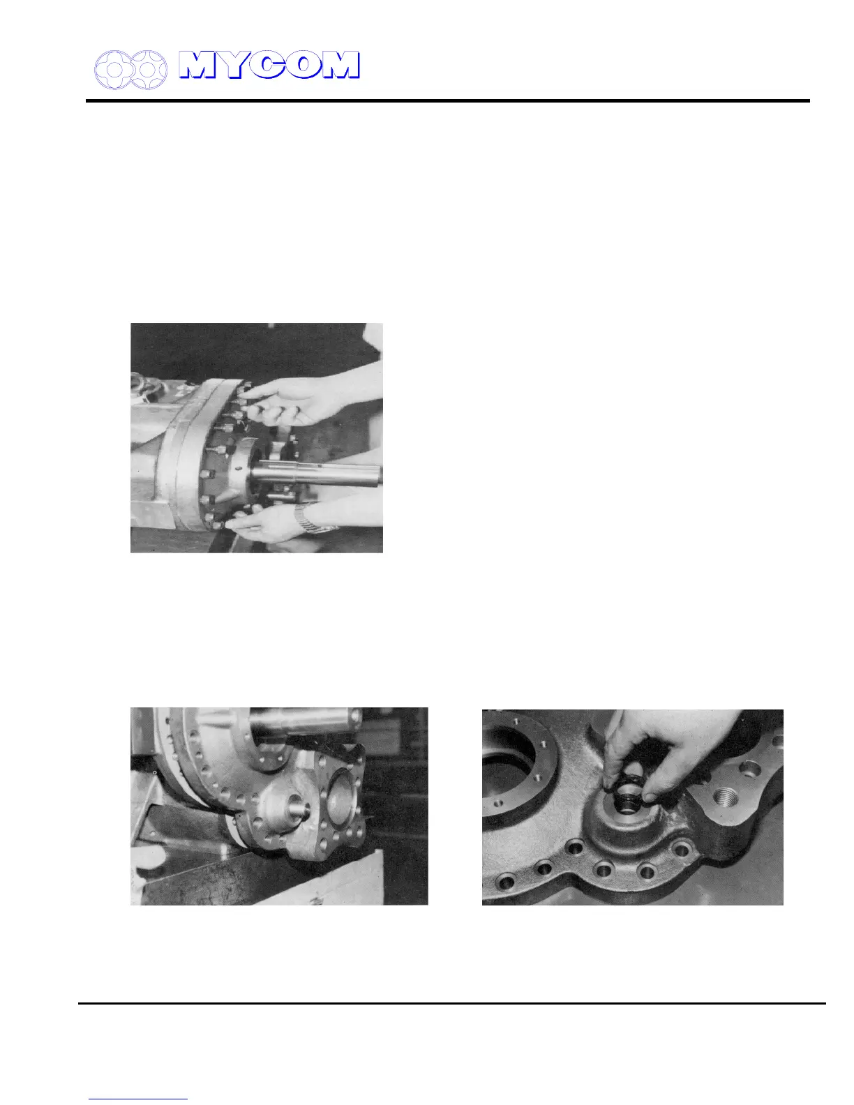
a) Remove all bearing cover fixing bolts (18-1, 18-2, 18-3) and insert one or two headless stud
bolts into holes in the top of the cover.
Fig. 48 Removing Bearing Cover Bolts (18-1, -2, -3)
b) Remove the cap on the Vi changing rod (444) and remove the lock nuts (453).
c) Threaded blind holes are provided at symmetric points on the bearing cover (16) (on recently
manufactured compressors these blind holes are closed with vinyl caps). Screw the bolts (18-
1, -2, -3) in evenly to press off the bearing cover.
When sufficient clearance is established, separate the gasket (17) from the flange face using a
spatula. Take care not to damage the gasket when removing.
Fig. 49 V
i
Changing Rod Section Fig. 50 O-Ring for V
i
Changing Rod (450)
d) The cover will come free of the parallel pin as clearance is increased. On Models 200a250, a
hanger bolt is provided on the top edge of the cover. Suspend the cover from a block before it
comes fully free.