REFRIGERATION DIVISION
V SERIES
SCREW COMPRESSOR HANDLING MANUAL
Supersedes all previous version. This information is for reference use only and subject to change without notice
Revision 2 (June 05,2000) Page 50 of 61
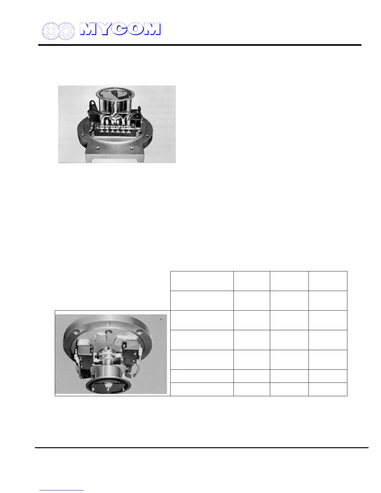
5. Disassembly and Adjustment of Unloader Indicator
The potentiometer (129), micro-switch (125) and micro-switch cam (127) are mounted in the
automatic control indicator portion of the compressor.
Fig. 107 106V**~250V** Standard Indicator
5.1 Disassembly and Adjustment of Unloader Indicator (120)
a) Remove the machine screw (140) securing the indicator pointer (139).
b) Remove the machine screw (138) securing the dial plate (137).
c) The potentiometer mounting plate (130) is fitted between the dial plate support (1) (134) and
dial support (2) (135).
Loosen and remove support (2) by turning counterclockwise while holding support (1)
securely.
d) When the right and left supports are removed, the potentiometer (129) can be removed
together with the mounting plate (130).
Automatic
Standard
Special
Specification
(1)
Special
Specification
(2)
Potential for slide
valve position
feedback
cc c
Micro-switch for slide
valve no-load position
signal
cc
Micro-switch for slide
valve full-load position
signal
c
Micro-switch for slide
valve special position
signal
d
Micro-switch cam for
standard actuation
cc
Micro-switch cam for
standard actuation
c
Fig. 108 System with Two Micro-Switches