REFRIGERATION DIVISION
V SERIES
SCREW COMPRESSOR HANDLING MANUAL
Supersedes all previous version. This information is for reference use only and subject to change without notice
Revision 2 (June 05,2000) Page 51 of 61
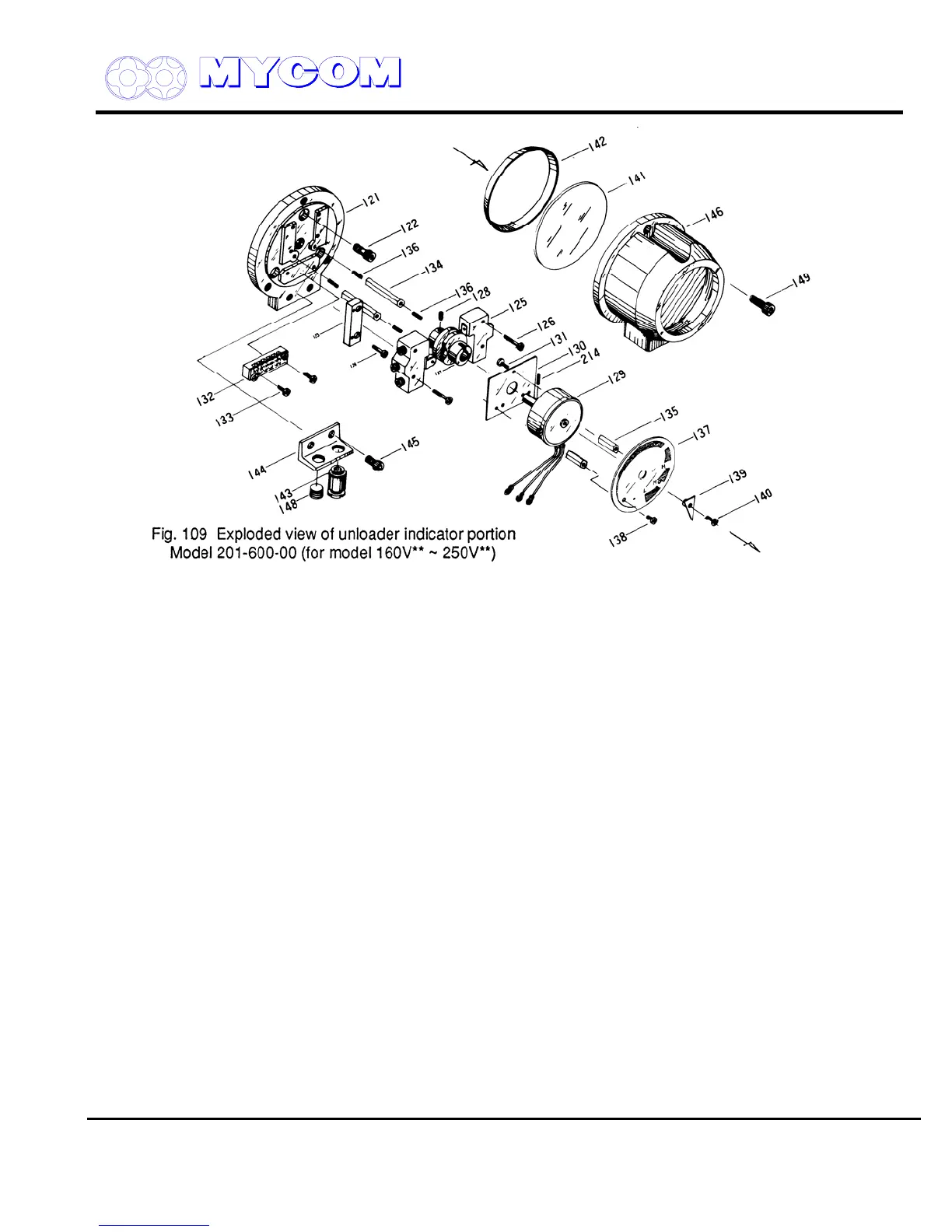
e) The potentiometer is secured to the mounting plate with three machine screws (131).
f) The micro-switch (125) is secured with two long machine screws (126).
Loosen these screws to remove the micro-switch.
The micro-switch component on the right side is for the no-load position signal and the one on
the left side is for the full-load position signal.
The micro-switch set plate (123), secured by other screws (124), is mounted under the left
side micro-switch component. The micro-switch component on the right side is for the no-load
position signal while the one on the left side is for the full-load position signal.
The micro-switch set plate (123), secured by other screws (124) is mounted under the left side
micro-switch component. Adjustment of the micro-switch is accomplished using with micro-
switch cam (127).
g) The terminal block (132) and other parts can be removed by removing the screws (133)
securing them.