1 2 3 4
ON ECE
SW1
1 2 3 4
ON ECE
SW1
1 2 3 4
ON ECE
SW1
1 2 3 4
ON ECE
SW1
1 2 3 4
ON ECE
SW1
10
Q81S_09_2021
JP6
FLASH
24V ac
max 20W
10 11
24Vac
230Vac
J5
JP3
JP8
JP9
1 2 3 4 5 6 7 8 9 10 11 12 13 14 15 16 17 18 19 20
JP1
JP2 JP3
TR2
C21
C24
POWER
230Vac
5A
230Vac
DL2
- + - +
SENS POWER
K4
C26
C27
K2
K3
- + - +
OP2
V1
FR1
SET SET TX
WORK BREAK
21 22
SW1 SW2
DL1 DL8
U2
1 2 3 4
ON ECE
1 2 3 4
ON ECE
PROTECO S.r.l. Via Neive, 77 - 12050 Castagnito (CN) ITALY Tel. +39 0173 210111 - Fax +39 0173 210199 info@proteco.net - www.proteco.net
3.9.1 Auxiliary radio channel AUX
To use the MRX01 interface as second radio channel, proceed this way
(see section 7.4):
Before setting the dip-switch SW1, make sure the power is OFF
MONOSTABLE COMMAND
The contact ACTIVATES when giving a start command by the remote control.
If you wish to choose this function mode, select the switches as follows:
1 = ON 2 = OFF 3 = OFF 4 = NO EFFECT
BISTABLE COMMAND
IThe contact ACTIVATES or DESACTIVATES every time you press the remote
control.
If you wish to choose this function mode, select the switches as follows:
1= OFF 2 = ON 3 = OFF 4 = NO EFFECT
TIMED COMMANDA
The contact ACTIVATES when giving a start command by the remote
control and stays for 90 seconds.
If you wish to choose this function mode, select the switches as follows:
1 = ON 2 = ON 3 = OFF 4 = NO EFFECT
3.9.2 Signalling LIGHT
TThe contact ACTIVATES at OPENING and DESACTIVATES only at FINAL
CLOSING POSITION.
If you wish to choose this function mode, select the switches as follows:
1= OFF 2= OFF 3= ON 4 = NO EFFECT
3.9.3 Courtesy LIGHT
The contact ACTIVATES at OPENING and DESACTIVATES after 90 from
complete duty cycle.
If you wish to choose this function mode, select the switches as follows:
1= ON 2= OFF 3= ON 4 = NO EFFECT
MRX01
jack
3.9 HOW TO PLUG THE 2 RADIO CHANNEL JACK
slideway
jack
MRX01
ATTENTION!:
CUT THE POWER OFF BEFORE PLUGGING THE INTERFACE
Plug the MRX01 jack (optional) onto connector J5, respecting the slot orientation.
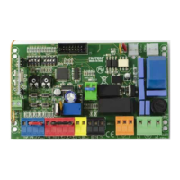
3.8 FLASHING LIGHT
EWire the flashing light (max 20W) to 10-11, terminal JP6.
• QUICK blinking → OPEN
• SLOW blinking → CLOSE
• FIXED light on → PAUSE
contatto
N.O.
 Loading...