5 of 32
www.NabcoEntrances.com OpusControlWiringandProgrammingInstallaonManual
Rev. 10-20-17 P/N C-00139
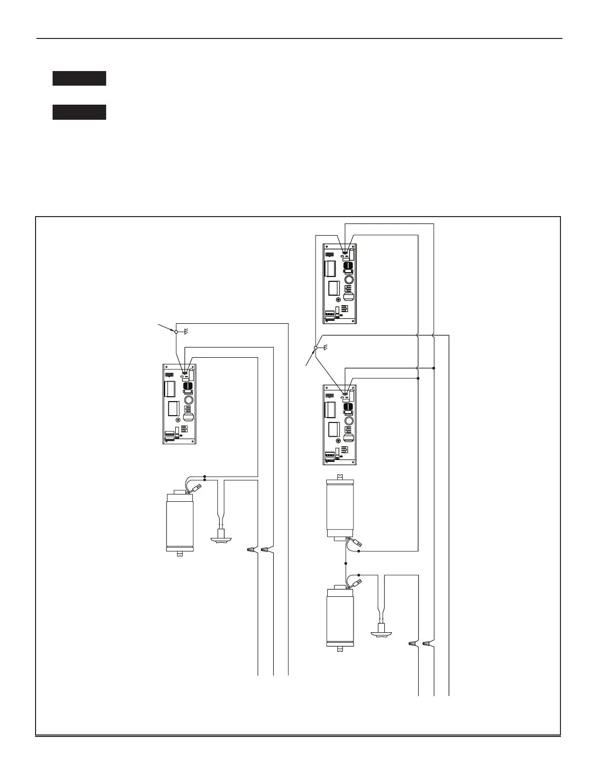
Keep sufcient spacing between high-voltage and low-voltage wiring. 120 VAC Power wires
must be routed (separate from other wiring) located near the top of inside Header.
Ensure that incomming electrical ground is properly secured to the grounding screw or
grounding wire, whichever is provided.
Aenon: Insert all Incoming 120 VAC Power wires into the pre drilled Electric Service Access Hole located at
the le or right side of Header End Cap.
Aenon: Electrical circuit to Nabco operator must not be not shared with other equipment such as lighng,
cash registers, or any device that might cause electrical interference on the circuit
Note: It is recommended for the Installer to house all Incoming 120 VAC wires within an Electrical Conduit.
SINGLE
120 VAC
SIMULTANEOUS PAIR
VAC
WHITE
BLACK
NEUTRAL
HOT
GROUND
OPUS CONTROL
BLACK
BLACK
1413121110
98
7
6
54
321
Ground Screw
ON/OFF
Rocker
Switch
WHITE
BLACK
NEUTRAL
HOT
GROUND
OPUS CONTROL
BLACK
BLACK
OPUS CONTROL
BLACK
WHITE
GREEN
GREEN
1413121110
98
7654321
1413121110
98
7654321
Ground Screw
ON/OFF
Rocker
Switch
Motor
2
1
Motor
BLACK
2
1
Motor
2
1