18 of 32
Opus Control Wiring and Programming Installaon Manual www.NabcoEntrances.com
P/N C-00139 Rev 10-20-17
CHAPTER 11: SWING DOOR WIRING DIAGRAMS
SECTION 11.1: Acvaon
DN 1329
1413121110
98
7
6
54
321
1413121110
98
7
6
54
321
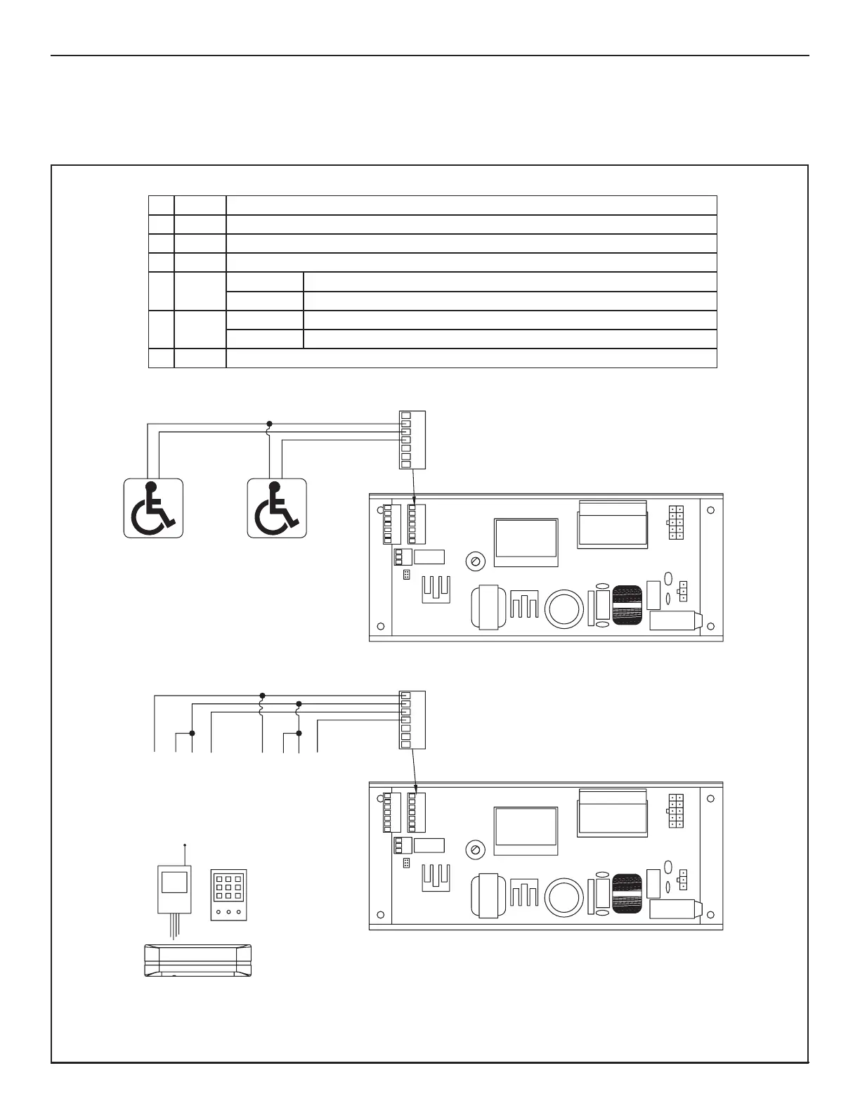
Exterior Push-Plate
Interior Push-Plate
COM
N.O.
3
2
4
COM
N.O.
All Devices Must Be
N.O. Dry Contact
Powered Activation Devices
(sensor, card reader, radio receiver, etc.)
Powered Activation Devices
Non-Powered Activation Devices
WARNING!
Total Power Consumption Of All Sensors And Powered Activation
Devices Must Not Exceed 750 mA
7
6
54
321
3
2
4
All Device Outputs Must Be
N.O. Dry Contact
7
6
54
321
CO .O.
PWR+ PWR-
1
CO .O.
PWR+ PWR-
Exterior ActivationInterior Activation
RADIO
RECEIVER
1 12VDC +12VDC
2 GND Common for 12V and Signals
361Interior Ac va on
462Exterior Ac va on/Programmable Input
56BSwing Door Con nuous Safety (door mounted, swing side Safety Sensor)
Slide Door Holding Beam
6SWL Swing Door Safety with Lockout (overhead, swing side safety sensor)
Slide Door Sidelite Sensor
7 Out1 Programmable Output
N
MN
M