W415-0973 / B / 08.28.13
23
IOM
10.0 TERMINATIONS
10.1 COMBUSTION AIR
10.2 EXHAUST
10.3 CONCENTRIC VENTING KIT
10.4 CONCENTRIC VENT TERMINATION INSTALLATION INSTRUCTIONS
H15.1
HORIZONTAL - The combustion air termination is
made up of a medium or long sweep 90° elbow pointing
downward to prevent rain from readily entering the
combustion air intake piping.
If the required clearance to grade cannot be obtained
with the “straight through” confi guration, the combustion
air intake pipe may be “periscoped” up to 24” (610mm) to
gain extra height (Figure 9)
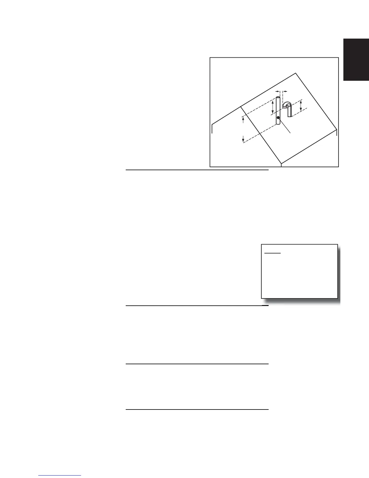
VERTICAL - The combustion air termination is made up
of a pair of medium or long sweep 90° elbow pointing
downward to prevent rain from entering the combustion
air intake piping.
The combustion air inlet must be located a minimum of
12” (305mm) above grade, and 12” (305mm) below the
exhaust outlet. (Figure 11)
12"
(305mm)
MIN.
3"
(76mm)
MIN.
18"
(457mm)
MIN.
12"
(305mm)
MIN.
ROOF TERMINATION
EXHAUST
FIGURE 11 - STANDARD VERTICAL VENTING
DETAIL
H15.2
HORIZONTAL - The exhaust termination is normally a 45° elbow or a medium or long sweep 90° elbow
pointing within 45° of the downward position, away from the combustion air intake terminal.
If the required clearance to grade cannot be obtained with the “straight through” confi guration, the exhaust
pipe may be “periscoped” up to 24” (610mm) to gain extra height. (Figure 9) In this case, the fl ue gases may
be expelled horizontally. Use the same size pipe as the interior run and count the fi ttings and length as part of the total
vent length.
If winter prevailing wind conditions are variable and likely to occasionally blow fl ue gases back in on the
combustion air intake, the exhaust termination may be raised 18-24” (457mm x 610mm) above the combustion
air intake terminal to take advantage of the natural buoyancy of the fl ue gases
to help prevent re-circulation of the exhaust. (Figure 9)
VERTICAL - No termination fi tting is required if venting vertically through a roof.
The end of the exhaust pipe must be 12” (305mm) higher than the entrance of
the combustion air intake terminal. (Figure 11)
The exhaust pipe extending through the roof must extend a minimum of 18”
(457mm) above any obstruction within an 18” (457mm) horizontal distance.
Insulate all venting that extends 24” (610mm) or more to the outside.
NOTE
Always clean out exhauster
collar after installation.
Vent pipe shavings from
initial installation can cause
blockage in the exhauster
collar drain.
H15.3.2
Concentric venting terminal kits may be used for this series furnace. They provide a means of obtaining
combustion air and exhausting products of combustion utilizing a single penetration through the exterior
wall. This can be useful when there is limited wall space available. Kits are available in 2” and 3” sizes. If
venting the 45K or 60K Btu/hr model with 1½” vent material, and a concentric vent kit is necessary, a increase
coupling may be used to connect to the 2” concentric venting kit. Read the instructions supplied with the kit for
additional installation instructions and details.
H15.4
Follow the concentric vent termination manufacturer instructions for installation of the concentric vent
termination kit. These instructions can be found by contacting the furnace manufacture. Furnace
manufacturer contact information is found on the front cover of this installation manual and operating
instructions.
10.5 LOCATION
 Loading...