Do you have a question about the Napoleon WSX-N Series and is the answer not in the manual?
Indicates an imminently hazardous situation that will result in death or serious injury.
Indicates a potentially hazardous situation that could result in death or serious injury.
Indicates a potential hazardous situation that may result in minor or moderate injury.
Highlights hazards of fire or explosion due to incorrect installation or operation.
Provides critical steps to take if a gas leak is detected, emphasizing safety and evacuation.
Warns about the dangers of carbon monoxide poisoning from flue gas infiltration.
A critical warning against installing the furnace in mobile homes due to safety risks.
Provides guidelines for selecting a furnace location, considering routing, access, and drainage.
A critical warning regarding installation on combustible floors, specifying wood flooring only.
A critical warning about the severe consequences of improper venting, including CO poisoning and fire.
A caution against using corrosive air sources for combustion, voiding warranty and causing damage.
Guidance on combustion air requirements for furnaces installed in unconfined spaces.
Guidance on combustion air requirements for furnaces installed in confined spaces.
A critical warning about the severe consequences of improper venting, including CO poisoning and fire.
Instructions for non-direct vent installations using indoor air for combustion.
Instructions for direct vent installations using outdoor air for combustion.
Details on supplying combustion air, including material requirements and sealing.
Guidelines for terminating combustion air intake pipes, including vertical and horizontal configurations.
Guidelines for terminating exhaust pipes horizontally and vertically, including considerations for wind and buoyancy.
A strict prohibition against common venting of multiple furnaces.
Requirements for draining condensate from the furnace, including trap assembly and hose connections.
Critical instruction that exhauster rotation is not permitted on these furnaces.
Guidance on conveying condensate from the drain trap assembly to a disposal system, avoiding freezing.
Critical caution against draining condensate outdoors or in areas prone to freezing.
A critical warning stating the furnace is designed for natural gas only and requires a conversion kit for LP.
Specifications for gas piping installation in accordance with Canadian and US codes, including flexible connectors.
Instructions for purging gas lines, emphasizing safety to prevent fire or explosion.
A critical warning against using open flames for leak detection in gas lines.
Guidance on converting the furnace for high altitude operation based on fuel type and location.
A critical warning that all regulator adjustments must be performed by qualified technicians.
Instructions for making electrical connections, ensuring compatibility and safety.
A critical warning to shut off power before making any electrical connections to prevent shock.
A critical warning not to disable the blower door safety switch due to shock hazards.
Information on using a single-stage thermostat with a two-stage furnace and heat anticipation adjustment.
Details on connecting and controlling an electronic air cleaner via the furnace control.
Procedure for safely starting the furnace for the first time.
Procedure for safely shutting down the furnace.
Describes the furnace's response and lockout procedures in case of flame failure.
Procedure for checking the temperature rise across the furnace to ensure correct airflow.
Instructions for inspecting, cleaning, or replacing the furnace air filter for optimal performance.
The operational sequence of the furnace, from thermostat call to blower operation and lockout.
Specific terms for the registered President's Limited Warranty, including duration and conditions.
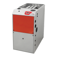
| Efficiency | Up to 96% AFUE |
|---|---|
| Heat Exchanger | Stainless Steel |
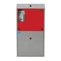
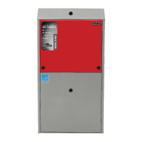
| Cabinet Type | Multi-Position |
| Fuel Type | Natural Gas |
| Heating Capacity | 40, 000 to 120, 000 BTU/h |
| Warranty | 10 Year Parts |