W415-3101 / B / 01.09.23
30
IOM
IOM
H16.3.4A
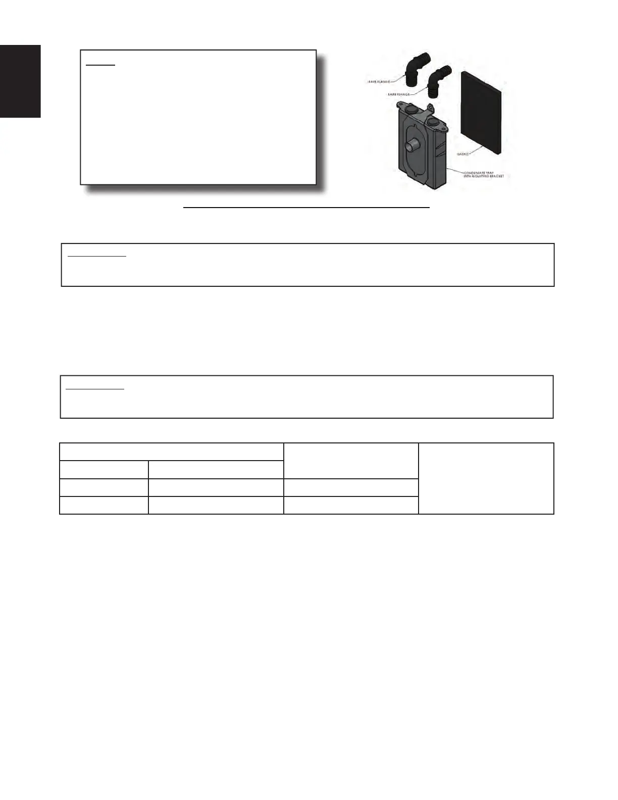
NOTE
• Condensate drain tubing must be cut to
appropriate length and slopping towards
condensate trap, ensuring that drain hoses
do not create traps prior to the condensate
trap assembly.
• Condensate trap must be primed with
water prior to initial furnace start up.
• Barbed fi ttings must be fully inserted into
condensate trap.
11.3 EXHAUSTER ORIENTATION & PRESSURE SWITCH LOCATION
Always secure or support the vent and intake to the fl oor joists or rafters to avoid sagging and possible
fatigue of venting materials. This ensures proper drainage and prevents spilling the products of combustion
into the building.
The blower compartment should be completely isolated from the burner compartment, and in tight rooms
with other combustion devices, be completely isolated from the room. Ensure that the combustion door
gasket is in good condition.
IMPORTANT:
KEEP PRESSURE SWITCH HOSES ABOVE FRONT MANIFOLD DRAIN, AND CUT TO
APPROPRIATE LENGTH TO PREVENT ANY SAGS OR TRAPS FORMING IN THE HOSES.
Orientation
Rotate Exhauster (Y/N)
See Figures 16 - 19 for
recommended mounting
Furnace Flue
Upfl ow Vertical N
Horizontal Right Right N
TABLE 5 - EXHAUSTER ORIENTATION
IMPORTANT:
THESE FURNACES DO NOT ALLOW FOR EXHAUSTER ROTATION. REFER TO FOLLOW
ILLUSTRATIONS FOR REFERENCE.
 Loading...