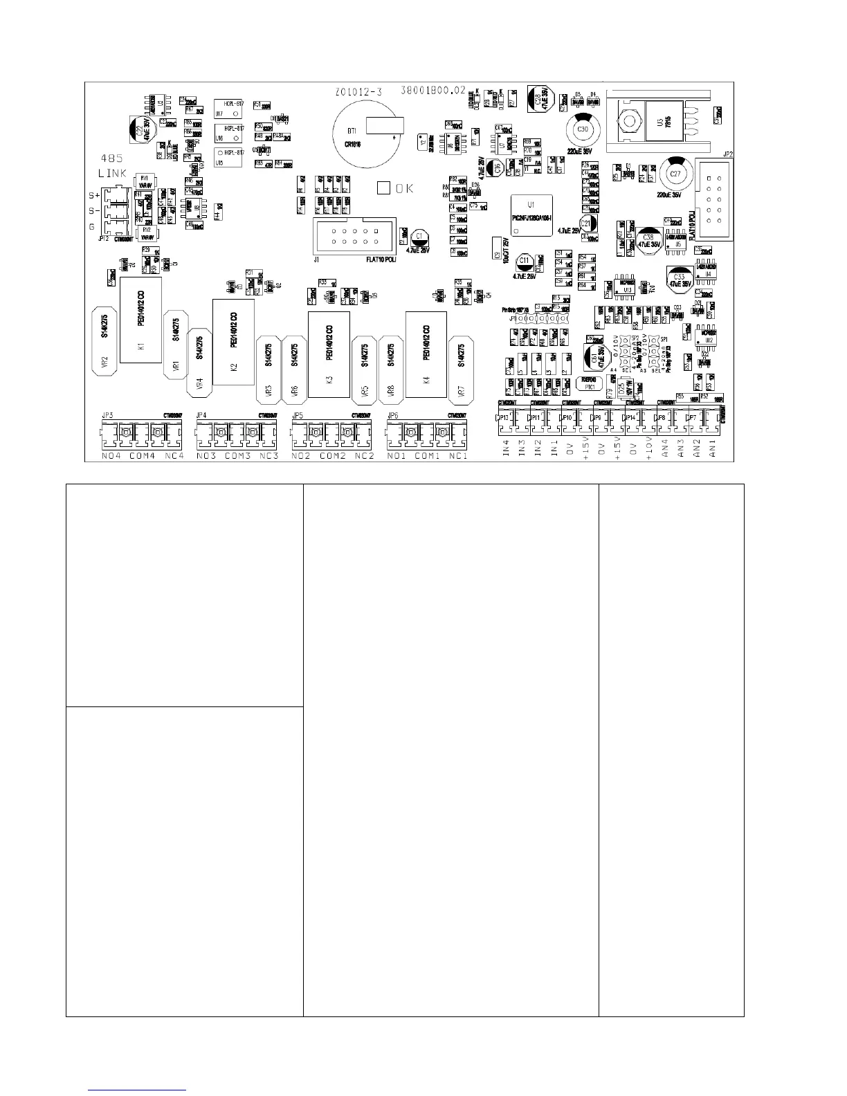
Analog inputs (10 or 15 Vdc):
1. AN1: 4-20 mA: pressure sensor
2. AN2: 4-20 mA: auxiliary
pressure sensor
3. AN3: 4-20 mA / 0 - 10 Vdc
(settable by jumper C.C.): flow
sensor or temperature sensor
4. AN4: 4-20 mA / 0 - 10 Vdc
(settable by C.C.): trimmer for
frequency regulation
Digital outputs:
motor run signal:
NO1, COM1: closed contact with motor
running.
NC1,COM1: closed contact with motor
stopped.
alarm signal
NO2,COM2: opened contact without alarm.
NC2,COM2: closed contact without alarm.
DOL1 pump relay:
NO3,COM3: closed contact with DOL1
running.
NC3,COM3: opened contact with DOL1
running.
DOL2 pump relay:
NO4,COM4: closed contact with DOL2
running.
NC4,COM4: opened contact with DOL2
running.
Relays are no voltage contacts. Max.
voltage to the contacts is 250 V with max
current of 5 A.
Digital inputs:
IN1
IN2
IN3
IN4
0V
We recommend using only no
voltage contacts.
Opening or closing the digital
contacts (depending on software
configuration set (see inst.
parameters) you can start or stop
the motor.