6-22 | ni.com
Chapter 6 Digital I/O
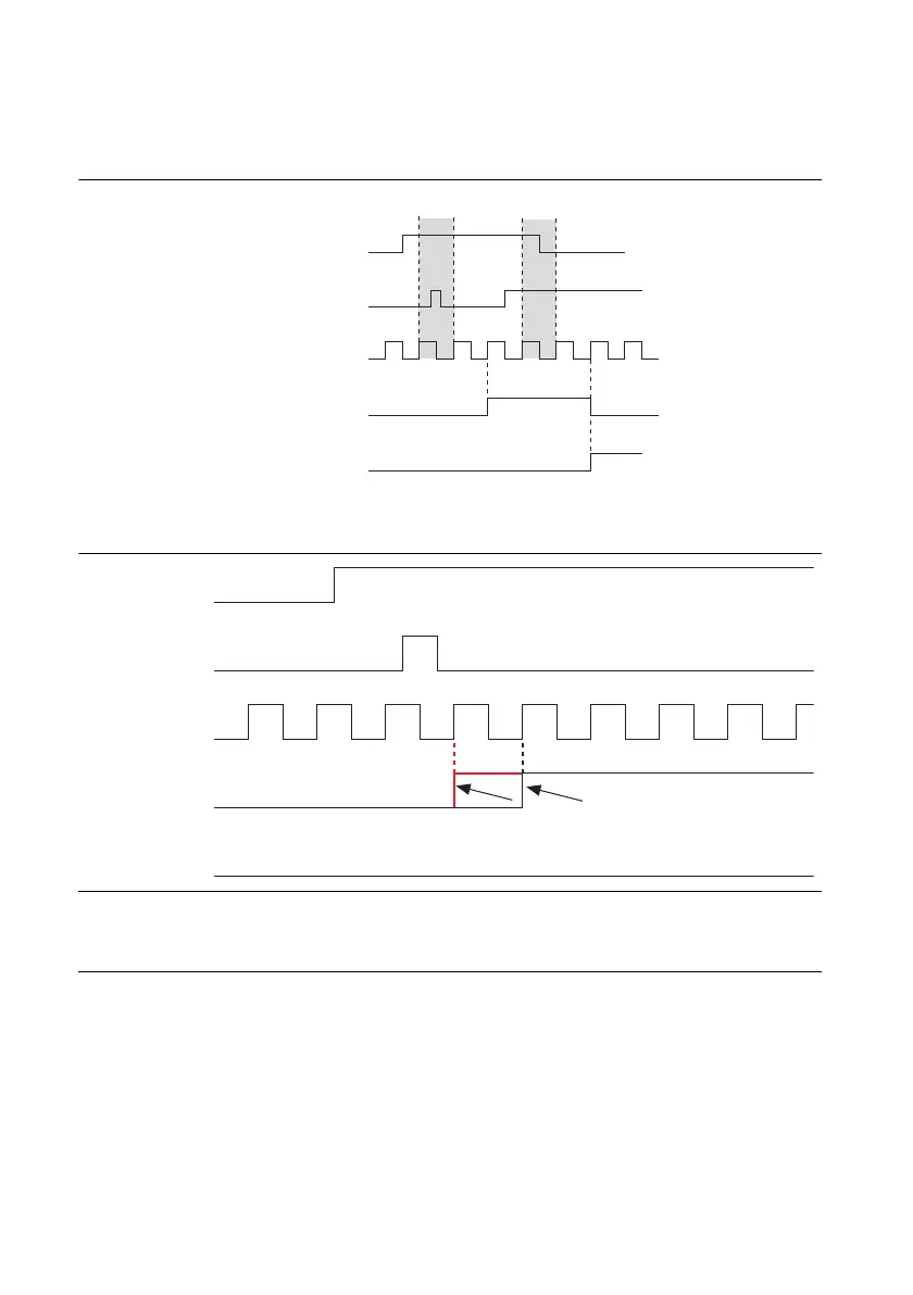
• Case 2—If an additional line on the bus also has a transition during the filter clock period,
the change is not propagated until the next filter clock edge, as shown in Figure 6-14.
Figure 6-14. Case 2
Figure 6-15 illustrates the difference between line and bus filtering.
Figure 6-15. Line and Bus Filtering
2A With line filtering, filtered input A would ignore the glitch on digital input P0.B and transition after two filter
clocks.
3A Filtered input A goes high when sampled high for two consecutive filter clocks and transitions on the next
filter edge because digital input P0.B glitches.
Digital Input P0.A
Digital Input P0.B
Filter Clock
Filtered Input A
Filtered Input B
Not Stable Not Stable
Digital Input P0.A
Digital Input P0.B
Filter Clock
Filtered Input A
Filtered Input B
1A
2A 3A

 Loading...