© National Instruments | 4-5
X Series User Manual
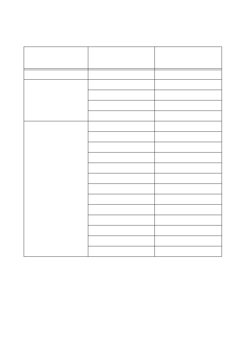
Table 4-2 shows how signals are routed to the NI-PGIA on MIO X Series devices.
For differential measurements, AI 0 and AI 8 are the positive and negative inputs of differential
analog input channel 0. For a complete list of signal pairs that form differential input channels,
refer to the
I/O Connector Signal Descriptions section of Chapter 3, Connector and LED
Information
.
Table 4-2. Signals Routed to the NI-PGIA on MIO X Series Devices
AI Ground-Reference
Settings
Signals Routed to the
Positive Input of the
NI-PGIA (Vin+)
Signals Routed to the
Negative Input of the
NI-PGIA (Vin-)
RSE AI <0..207> AI GND
NRSE AI <0..15> AI SENSE
AI <16..79> AI SENSE 2
AI <80..143> AI SENSE 3
AI <144..207> AI SENSE 4
DIFF AI <0..7> AI <8..15>
AI <16..23> AI <24..31>
AI <32..39> AI <40..47>
AI <48..55> AI <56..63>
AI <64..71> AI <72..79>
AI <80..87> AI <88..95>
AI <96..103> AI <104..111>
AI <112..119> AI <120..127>
AI <128..135> AI <136..143>
AI <144..151> AI <152..159>
AI <160..167> AI <168..175>
AI <176..183> AI <184..191>
AI <192..199> AI <200..207>

 Loading...