Chapter 3 Configuring Your SCXI Hardware and Software
Getting Started with SCXI 3-42 www.ni.com
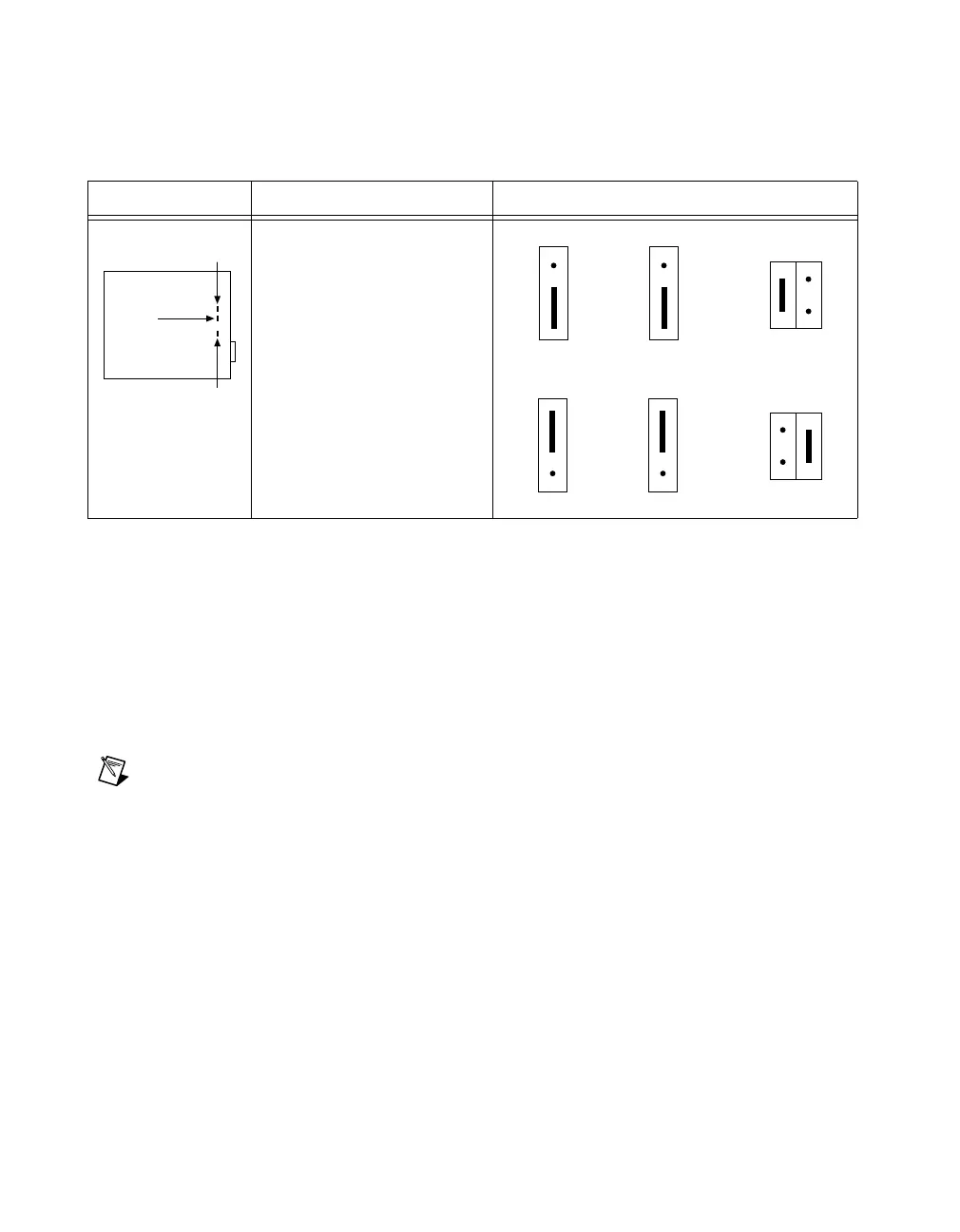
Table 3-32 shows the SCXI-1162 device-type jumper configurations.
SCXI-1162HV Module
The SCXI-1162HV module consists of 32 optically-isolated, wide range,
AC or DC digital inputs. The SCXI-1162HV is a module used for sensing
the presence of AC or DC voltages.
To configure the SCXI-1162HV module, use the six user-configurable
jumpers (W2–W7). (Jumper W1 is a reserved jumper and should remain
unconnected.)
Note
If you are controlling the SCXI-1162HV through the SCXIbus and are not
connecting a DAQ device directly to the rear connector of the SCXI-1162HV, the positions
of these jumpers are irrelevant.
Jumper W3, when set to position P, connects a 2.2 kΩ pullup resistor to the
SERDATOUT line. An open-collector driver either actively drives low or
goes to a high-impedance state, relying on a pullup resistor to make the
signal line go high. If too many pullup resistors are attached to the
SERDATOUT line, the drivers cannot drive the linelow. To prevent this, set
jumper W3 to position P on only one of the SCXI-1162HV modules cabled
to the DAQ device in a multichassis system. It does not matter which of the
SCXI-1162HV modules cabled to the DAQ device has the pullup
connected.
Table 3-32. SCXI-1162 Device-Type Jumper Configuration
Jumper Description Configuration
MIO—Use this setting to
configure the rear connector
foranAIorMIOdeviceor
Lab/1200deviceinserial
mode (factory-default
position).
DIO—Use this setting to
configure rear connector for
a DIO device in serial mode.
W6
W4
W3
DIO
MIO
W3 W4
DIO
MIO
PAR
W6
MIO
DIO
PAR
W6
W3 W4
DIO
MIO
DIO
MIO
MIO
DIO
 Loading...