Chapter 6 Digital I/O
X Series User Manual 6-26 ni.com
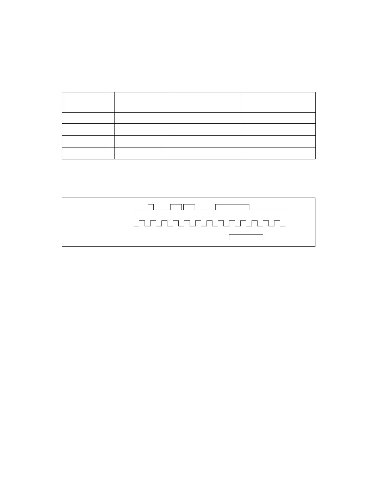
The filter setting for each input can be configured independently. On power
up, the filters are disabled. Figure 6-12 shows an example of a low-to-high
transition on an input.
Figure 6-12. Input Low-to-High Transition
When multiple lines are configured with the same filter settings they are
considered a bus. There are two filtering modes for use with multiple lines:
line filtering and bus filtering. With line filtering, each line transitions
independently of the other lines in the bus and acts like the behavior
described above. With bus filtering, if any one line in the bus has jitter then
all lines in the bus will hold state until the bus becomes stable. However,
each individual line will only wait one extra filter tick before changing.
This prevents a noisy line from holding a valid transition indefinitely. With
bus mode if all the bus line transitions become stable in less than one filter
clock period and the bus period is more than two filter clock periods, then
all the bus lines are guaranteed to be correlated at the output of the filter, as
shown in the figure.
Table 6-1. Filters
Filter Setting Filter Clock
Pulse Width Guaranteed
to Pass Filter
Pulse Width Guaranteed
to Not Pass Filter
Short 12.5 MHz 160 ns 80 ns
Medium 195.3125 kHz 10.24 μs 5.12 μs
High 390.625 Hz 5.12 ms 2.56 ms
None — — —
Digital Input P0.x
Filter Clock
Filtered Input
11 211 21
Artisan Technology Group - Quality Instrumentation ... Guaranteed | (888) 88-SOURCE | www.artisantg.com

 Loading...


