Chapter 3 Connector and LED Information
© National Instruments 3-5 X Series User Manual
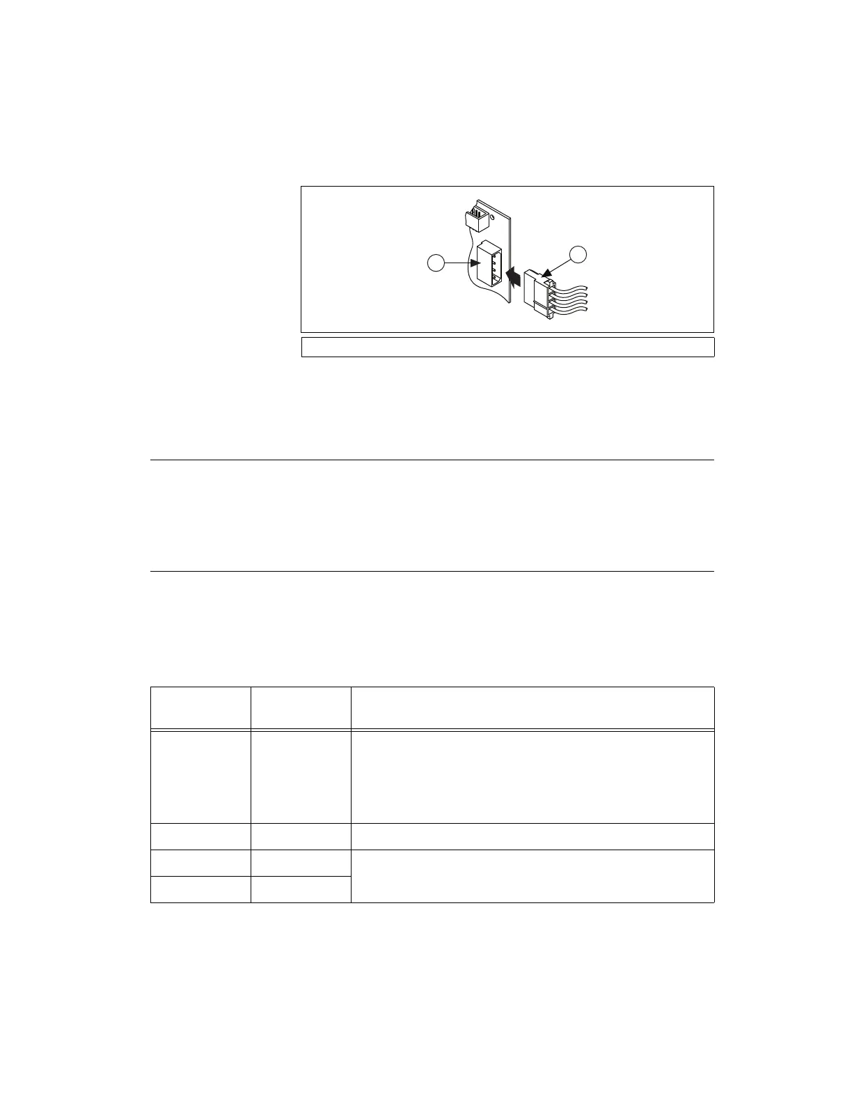
Figure 3-1. Connecting to the Disk Drive Power Connector
4. Replace the computer cover, and plug in and power on the computer.
RTSI Connector Pinout
(NI PCIe-632x/634x/635x/636x Devices) Refer to the RTSI Connector Pinout
section of Chapter 9, Digital Routing and Clock Generation, for
information about the RTSI connector on PCI Express X Series devices.
USB Device LED Patterns
(NI USB-634x/635x/636x Devices) X Series USB devices have LEDs labeled
ACTIVE and READY. The ACTIVE LED indicates activity over the bus.
The READY LED indicates whether or not the device is configured.
Table 3-2 shows the behavior of the LEDs.
1 Device Disk Drive Power Connector 2 PC Disk Drive Power Connector
Table 3-2. LED Patterns
ACTIVE
LED
READY
LED
USB Device State
Off Off The device is not powered or not connected to the host
computer, or the host computer does not have the correct
version of NI-DAQmx. Refer to Table 2-1, XSeries
NI-DAQmx Software Support, for the NI-DAQmx support
information for your device.
Off On The device is configured, but there is no activity over the bus.
On On The device is configured and there is activity over the bus.
Blinking On
Artisan Technology Group - Quality Instrumentation ... Guaranteed | (888) 88-SOURCE | www.artisantg.com

 Loading...


